This thread has been locked.

If you have a related question, please click the "Ask a related question" button in the top right corner. The newly created question will be automatically linked to this question.

DIGITAL POWER CONTROL

Other Parts Discussed in Thread: UCD3138128, LM5066I, UCD3138

HELLO

I DESIGN POWER INVERTERS WITH SINE WAVE OUTPUT AT 115 VRMS 50HZ TO 1KHZ AND I WOULD LIKE TO NO THAT IF I WONTED TO TRY AND DESIGN A INVERTER SYSTEM CAN I USE SOMETHING LIKE THE UCD3138128 CONTROLLER AND ALSO A PART LIKE THE LM5066I WHICH WILL BE USED FOR THE INPUT VOLTAGE CONTROL FOR SPIKES AND OTHER TRANSIENTS ON THE LINE , NOW IN ORDER FOR ME TO KEEP THE SIZE AND WEIGHT DOWN I WILL NEED TO SWITCH THE FULL BRIDGE SECTION LIKE A CLASS D AMP WITH A SINE WAVE REF. SIGNAL, SO LET SAY WITH NO SINE WAVE REF THE FULL BRIDGE JUST SWITCH AT 200 KHZ SQ. WAVE AND AS SOON AS I START TO APPLY A SINE WAVE REF. SIGNAL THE THE HI-VOLTAGE SQ. WAVES START TO MODULATE SO ON THE OTHER SIDE OF THE OUTPUT TRANSFORMER WHICH WILL BE WOUND TO OPERATE AT HI- FREQ. THE SEC. SIDE WILL GO THRU A LOWPASS FILTER AND I GET THE SINEWAVE OUT AT A VOLTAGE VS. THE AMPLTD. OF THE SINE REF SIGNAL SO FROM THE OUTPUT I WILL HAVE A SMALL TRANSFORMER RATED AT 5HZ TO 2KHZ RANGE AND THIS WILL BE THE FEEDBACK TRANSFORMER I DIVIDE THAT DOWN TO A POINT TO WHERE ITS NOW REGULATING THE OUTPUT BASED ON THE MATCH OF THE FEEDBACK AND THE SINE REF SIGNAL SO IF I LOAD THE OUTPUT, THE UNIT WILL ADJ. THE

OUTPUT VOLTAGE TO REMAIN CONSTANT.  NOW WHAT TYPE OF MODULATION  SHOULD I USE BASED ON THE SELECTED PARTS ARE THE PART FOR THE CONTROLLER, WHAT SOFTWARE SHOULD I USE AND IS IT VERY HARD TO USE ARE TRY TO DESIGN A DIGITAL POWER SYSTEM, THE PMBUS CABLE

WHAT TYPE OF CABLE IS THIS, WHERE DO I GET ONE FROM ARE CAN I MAKE ONE OF MY OWN, IS THERE DRAWINGS FOR THE CABLE ARE CAN YOU EMAIL ME BACK A LIST OF THINGS THAT I WILL NEED TO GET GOING MY EMAIL IS ( wlmccain@mccainlab.com )

THANKS A LOT FOR ALL YOUR HELP AND TIME ,

WILLIE L. MCCAIN

  • You will need a USB interface adapter. www.ti.com/.../usb-to-gpio I think this is what you are referring to as a PMBus cable. It's a hardware adapter that you plug into a USB socket on a PC, and it works with our Fusion Digital Power Designer GUI. www.ti.com/.../fusion_digital_power_designer

    The Fusion Digital Power Designer is designed to work with our EVMs, and we don't have an inverter EVM. So what you really need is the Device GUI which is part of the Fusion Digital Power Designer. It permits you to download and debug your programs, but doesn't include the higher level power supply functions that go with the EVM codes. Then we recommend CCS (Code Composer Studio) 6.1 as a development tool.

    Since we don't have an EVM, I'd suggest starting with the training labs, see here:

    e2e.ti.com/.../292514

    On the UCD3138 family, you put your desired output on the EADC DAC, and the actual output on the EADC. (EADC stands for Error ADC) The EADC will give you high speed digital information on the difference between the desired output and that actual input. This is run through a digital filter with programmable coefficients, and the output of the filter controls the PWM pulse width on the Class D amplifier. (or the phase shift on a phase shifted system, or the frequency on an LLC, or a combination on mixed mode systems).

    We don't have an EVM or even a code example for an inverter, so far as I know. On our PFC, we read the input voltage and use it to set the target for output current on the EADC DAC. That's the closest we get to what you want. Presumably on an inverter, you would put the target output voltage from your sine wave on the EADCDAC, and put the actual voltage into the EADC.
  • OKAY LET ME SEE IF I ALMOST UNDERSTAND,
    AS FAR AS THE CABLE I WOULD USE A REGULAR USB CABLE THAT WILL PLUG INTO THE USB PORT ON THE FRONT OF MY PC ,THE USB CABLE HAS THE REQUIRED PINS FOR THE PMBUS TO PROGRAM THE PART UCD3138128 AND THE LM5066I WHICH BOTH OF THE PARTS WILL BE ON MY PC BOARD FOR TESTING, NOW I HAVE A PMBUS FROM BOTH PARTS, SHOULD I PUT ALL THE REQUIRED PINS TOGETHER AND THAN THE FUSION DESIGNER SHOULD DETECT BOTH PARTS AND I WILL SELECT THE PART I WONT TO SETUP / ARE SHOULD I HAVE THE LINES FROM BOTH PARTS SEPARATE SO MY BOARD WILL HAVE TO USB PORTS, ONE TO THE UCD3138 AND THE OTHER PORT FOR THE OTHER DEVICE.

    NOW I DOWNLOAD THE ( Fusion Digital Power Designer GUI ) AND THE ( CCS (Code Composer Studio) 6.1 ) FROM THE WEBSITE AND THIS SOFTWARE WILL DETECT THE DEVICES IS THIS CORRECT?.

    SO NOW I HAVE A SINEWAVE REF SIGNAL AT BOTH 60HZ AND AT 400HZ SO I WILL TAKE THE SIGNALS( ONE AT A TIME THRU FREQ. SELECT
    ON MY PC BOARD ASSY AT THIS POINT THE REF SIGNAL IS OFF SO THE OUTPUT IS JUST FREE-RUNNING AT 200KHZ SQ. WAVE ACROSS THE FULL BRIDGE SECTION AND AT THE OUTPUT OF THE LOW-PASS FILTER I SHOULD SEE ZERO VOLTS , NOW WHEN I START TO INCREASE THE REF. SIGNAL THE DRIVER SECTION SHOULD START TO MODULATE AT THE REF. SIGNAL 60HZ / ARE 400HZ ,NOW THIS REF SIGNAL SHOULD GO TO ONE INPUT OF THE A/D AND LET SAY AT 1.25VRMS THE OUTPUT SHOULD BE AT 125 VRMS MY BUS VOLTAGE FOR THE FULL BRIDGE SECTION WILL BE AROUND 350VDC ARE SO. SO NOW WHAT I WILL DO IS INCREASE THE AMPLTD. OF MY SINE REF.UNTIL I GET TO A LEVEL BEFORE IT MAX. OUT AND I ADJUST THE FEEDBACK SINEWAVE INTO ANOTHER A/D UNTIL I SEE THE OUTPUT DROP DOWN TO LET 117 VRMS, SO NOW AT THIS POINT AS I LOAD THE OUTPUT THE CONTROLLER WILL TRY TO KEEP THE OUTPUT THE SAME UNTIL I GET TO A POINT OF CURRENT LIMIT AND THE UNIT GOES INTO HICCUP / ARE SHUTDOWN FOR 5 SEC'S AND TRY TO COME BACK UP AGAIN IF THE PROBLEM / ARE CONDITION IS STILL PRESENT IT WILL SHUTDOWN AGAIN ARE ENTER HICCUP MODE UNTIL THE CONDITION IS CLEARED AND THAN THE SYSTEM RUNS NORMALLY..

    OKAY MY FINIAL GOAL HERE IS ONCE THE UNITS ARE ASSEMBLED THEY WILL GO TO THE FINIAL TEST SECTION AND THE TECHNICIANS THERE WILL PLUG THE UNIT UP AND SET THE PARAMETERS UP FOR THE SYSTEM AND THAN LOAD THE UNIT TO MAKE SURE CURRENT LIMIT POINT IS CORRECT, OUTPUT VOLTAGE IS CORRECT( AC VOLTAGE ), DC INPUT OVER AND UNDER VOLTAGE DET. POINT IS CORRECT, SET THE TEMP CONTROL WHERE I WILL USE A A/D CONVERTER WITH A THERMISTOR AND WHEN THE TEMP GET TO A CERTAIN POINT THE FAN TURNS ON UNTIL IT COOLS DOWN AND IF THE FAN FAILS THE TEMP WILL GO OVER THE SET POINT AND CAUSE THE UNIT TO SHUTDOWN SO I WILL NEED TO USE ONE OF THE GPIO PIN AS A CLOCK OUT THAT WILL GOT TO A MOSFET TO RUN THE FAN , SET AC OVER VOLTAGE POINT AND WHEN THIS IS DONE THE PERSON WILL UNPLUG THE UNIT AND THE PAPER WORK THAT COME WITH THE UNIT WILL BE TEST SIGN OFF OF ALL THE REQUIRED TEST POINT THAT WILL GO WITH THE UNIT AND IS RAPPED AND READY TO GO . DO YOU THINK IAM MAKING SENSE HERE,
    SO WHEN THE UNITS ARE ASSEMBLED THEY ARE DUM UNTIL THEY ARE SET ......

    LET ME NO, THANKS SO MUCH MR. BOWER FOR ALL YOUR TIME THIS WILL BE A FIRST FOR ME BUT I HAVE A GOOD CONTRACT COMMING UP FOR BOTH MILITARY AND AEROSPACE APPLICATIONS , EVERYTHING FROM ON-BOARD AC POWER TO COCKPIT HI-POWER LED LIGHTING ASSY, EMERG. EXIT LIGHTS HI-POWER LANDING LIGHT ASSY AND MORE SO IAM TRYING TO GET SETUP NO AND TRY TO START LEARNING HOW THIS IS DONE BECAUSE THIS WILL GO INTO 7 TO 10 YR. PHASES ON ALL THE DESIGNS

    LET ME NO IF I HAVE THE CORRECT IDEA.

    THANKS,
    WILLIE L. MCCAIN
  • Willie, I think you are missing a couple of vital steps in your description.

    1. You can't use a regular USB cable - you need the specific adapter I mentioned. It's the only thing that will work with the GUI. I don't know anything about the LM5066i.

    2. The UCD3138 is a firmware driven device. We don't provide any firmware for an inverter. You can try some of our other firmware for examples of pieces, but we only have firmware for power supplies. The key parts of your inverter firmware you are going to have to write essentially from scratch.
  • While the LM5066I is a PMBus compliant device, it is not directly supported with the Fusion Digital Power Designer SW.

    This device has its own GUI that can be found under the Tools & Software tab on the LM5066I product page, it is called PI-Commander.

    If the LM5066I uses the same type dongle (USB-to-GPIO) for communication then it is likely that there will be problems trying to communicate while using both the Fusion GUI and the PI-Commander if both devices are on the same PMBus segment, but I have no experience using the PI-Commander.  This is a SW/dongle issue, both these devices should coexist on the same segment if they have a common host.

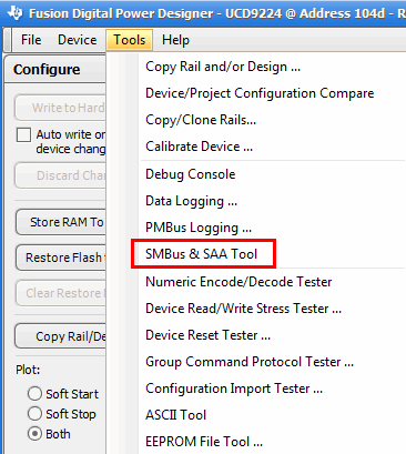
    While the LM5066I is not directly supported by the Fusion GUI, the SW does have the capability to read/write just about any PMBus/I2C command by using the SMBus & SAA Tool

    If you use this tool while connected within the Fusion GUI, as shown below, you may need to turn off the polling function within the Monitor page.

    This tool is also available standalone from the Fusion GUI SW Folder by navigating to  Start --> All Programs --> Texas Instruments Fusion Digital Power Designer --> Tools --> SMBus & I2C & SAA Debug Tool (different name, same tool)

    For additional support with the LM5066I, I would suggest posting to the Hot Swap Forum.