This thread has been locked.

If you have a related question, please click the "Ask a related question" button in the top right corner. The newly created question will be automatically linked to this question.

UCD3138: DPWM generates too small pulses

Part Number: UCD3138

Hi,

I run into a problem and found out, that the DPWM generates too short pulses.

Yes, I know, there were settings to prevent this, but unfortunately it fails. Is this a known issue?

Here my test setup.

I config my three DPWMs (three Phase System) to get the duty cycle from the filter section. The filter section is set up to get the input from the CPU. When I set the filter input to 1 manually the output runs up until the max. possible pulse width (here 3.3µs) is reached, thats ok. When I set the value to -1 than the pulses getting smaller and smaller until no pulses were generated any more. I set Minimum Duty Mode = 1, so the minimum pulse width is determined by the value in the DPWMMINDUTYLOW register. Unfortunately I see pulses down to 30ns.

Using Minimum Duty Mode = 2 the pulses getting smaller and smaller and the system ends up by generating pulses with the minimal pulse width programmed. This works fine. So I am sure, that the value in DPWMMINDUTYLOW is correct.

Whats wrong???

With best regards

Gerhard

  • Hi Gerhard,

    The MIN_DUTY_MODE bits selects how the DPWM handles minimum duty cycle limits.
    • 0 - Default, Filter output is passed directly through to the DPWM
    • 1 - Filter value passed through if above DPWMMINDUTYLOW. If below DPWMMINDUTYLOW, no pulse from DPWM
    • 2 - Filter value passed through if above DPWMMINDUTYLOW. If below DPWMMINDUTYLOW, DPWM pulse width = DPWMMINDUTYLOW

    So you should see no pulse when you set to 1 and applied -1 as the error. Can you tell me what's your DPWMMINDUTYLOW value?

    Regards,
    Bosheng Sun
  • Hi,

    thanks for your reply.

    I know this and so I use MIN_DUTY_MODE = 1. I expected, that the DPWM output stops and the shortest (last ?) pulse is not shorter than defined in DPWMMINDUTYLOW. DPWMMINDUTYLOW is set to 65 and this register should have 4ns resolution, or I am wrong?

    I defenetely see pulses down to 30ns, which is not correct.

    Setting MIN_DUTY_MODE = 2 gives the programmed minimal pulse length, so I think, the value in DPWMMINDUTYLOW is ok.

    Unfortunately my system isn't a common power supply, it is a constant current source. The power range is some mW to 200W. Sometimes I have to generate 100µA into some mega ohms and this isn't possible using MIN_DUTY_MODE = 2.

    I need CC/CV behaviour and some kind of light load mode, like stopping the DPWMs for long intervals.

    By the way, I never get the Light Load modul running. As I Need CC/CV, I think, the LL isn't usable in my app.

    With best regards

    Gerhard
  •  Hi,

    The resolution depends on how you write 65 to the register. if you write to the whole register:

    Dpwm0Regs.DPWMMINDUTYLO.all = 65, then it is 250ps

    if you write as:

    Dpwm0Regs.DPWMMINDUTYLO.bit.MIN_DUTY_LOW = 65, then it is 4ns

    With  MIN_DUTY_MODE = 1, you should see zero duty in your case.

    Are you trying to use DPWMMINDUTYLO to provide minimum duty? You can achieve this by using filter clamp register FILTEROCLPLO. Have you tried that?

    Regards,

    Bosheng

  • Hi,

    I wrote Dpwm0Regs.DPWMMINDUTYLO.bit.MIN_DUTY_LOW = 65.

    I Need some Kind of hicup mode to deal with very light loads. I see some fluktuations at the Output and cant  do anything against it by modifying P, I or D of the filter. So I guess, that the System gets very unlinear as the switching of my Transistors isn't that clean.

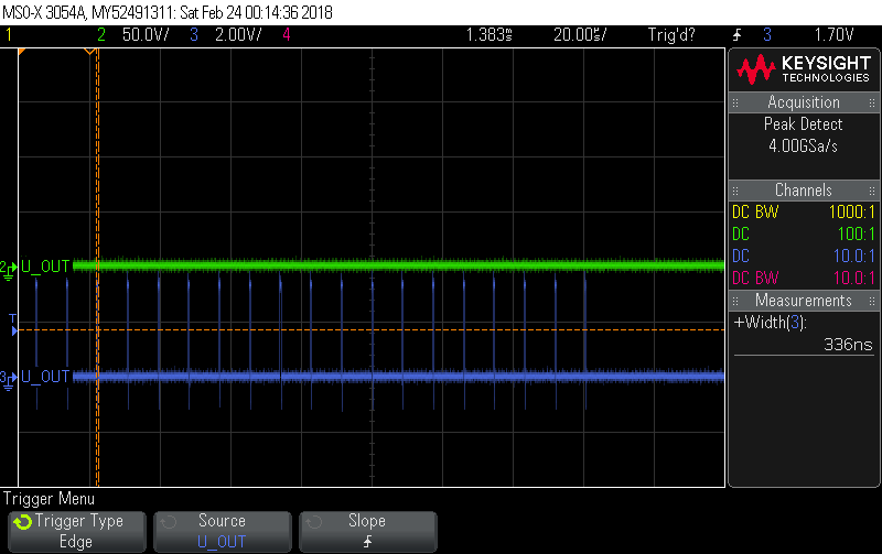
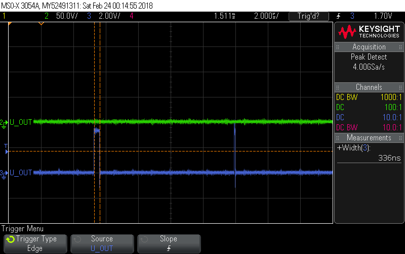
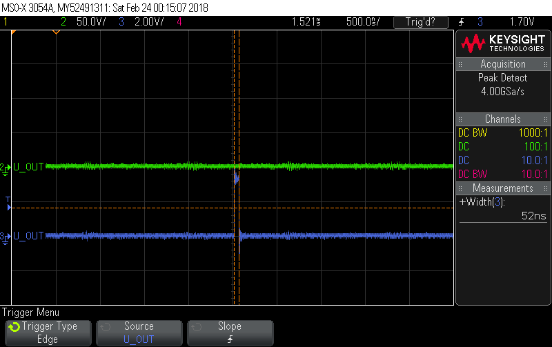
    But I get some Screen shots now. I Looks like, that only the last puls emitted is too short. At very light load there will be only one pulse followed by a longer interval without pulses and this results in a sequence of too small pulses I detected before.

    Here is an overview about whats happen when I set error o -1- The lable 'U-Out' is wrong, sorry for that.

    Here you see the n-1 pulse which has the width of about 336ns and the last pulse which is smaller.

    And here is the very last pulse, which is 52ns ==> too short.

    With best regards

    Gerhard

  • Gerhard,

    What did you put on MIN_DUTY_HIGH? What is the minimum pulse width you need?

    I am not clear what exact you want to achieve with this minimum duty register. If you want the minimum duty is always higher than a certain value, you can use

    Filter Output Clamp Low Register (FILTEROCLPLO).

    Regards,

    Bosheng

  • Hi,

    I want to archive, that the pulse generation stops if the filter output is lower than a certain value and starts again, if the filter output is higher than an other certain value. This two values go into MIN_DUTY_LO and MIN_DUTY_HI registers.

    When the requested output power is low enough, the DPWM generates bursts (BURST_MODE = 1) and this bursts only contain pulses of a width greater or equal MIN_DUTY_LO.

    Clamping the filter output does NOT gererate bursts, and so for the converter delivers too much energy to the load.

    With best regards

    Gerhard

  • Gerhard,

    I just tested MIN_DUTY_LO and MIN_DUTY_HI registers, if you put the same value for them, it will do what you need: the pulse generation stops if the filter output is lower than this value and starts again, if the filter output is higher than this value. If you put different values on MIN_DUTY_LO and MIN_DUTY_HI, then the minimum duty is controlled by MIN_DUTY_HI.

    Can you use the same value for MIN_DUTY_LO and MIN_DUTY_HI ?

    Regards,
    Bosheng
  • Gerhard,

    Any update? Is this issue still pending? If not, can we close it?

    Regards,
    Bosheng
  • Bosheng,

    sorry for the delay. My mother (97) was brought to hospital and I have to organize a lot .. so no time for further investigations.

    I am now in my office again and try out some other parameter combinations. I will come up with an update until next week.

    Sorry again.

    With bet regards

    Gerhard