This thread has been locked.

If you have a related question, please click the "Ask a related question" button in the top right corner. The newly created question will be automatically linked to this question.

CCS/UCD3138: UCD3138: current share function

Part Number: UCD3138

Tool/software: Code Composer Studio

Hello, I was recently learning the UCD3138HSFBEVM_029 demo board .

I met some questions about the current sharing mode.

Firstly, I made two boards in current sharing operation. The test  results showed the current sharing ratio in steady state is nearly perfect, when Vin is at 36V and load is over 40A. But when Vin is higher and load is lower, the the current sharing ratio wasn't as good as in before situations. So I expect to know what causes and what factors affect  the current sharing ratio?

Secondly,I read the codes about handle_current_sharing(void), there are current_share_ki, and current_share_kp parameters, Whether these parameters have an effect on current sharing ratio in deferent operation situations?Is there any possibility to ensure the current sharing ratio is good  no matter the bords works at  a larger range of Vin or a a larger range of load ?if it can be realized, what should I do? please give me some suggestions, thank you very much!

Thirdly,  I read the code:

void enable_current_sharing(void)
{
#ifdef CURRENT_SHARING_ENABLE
FeCtrl0Regs.EADCDAC.bit.DAC_DITHER_EN = 1;
//3 for pass through
//1 for DPWM current source control 250 uA into 10 kOhm at 100% duty cycle.
MiscAnalogRegs.CSCTRL.bit.TEST_MODE = 1;
//300 kHz
MiscAnalogRegs.CSCTRL.bit.DPWM_PERIOD = 108;
// MiscAnalogRegs.CSCTRL.bit.DPWM_DUTY = 54;
#endif
}

MiscAnalogRegs.CSCTRL.bit.DPWM_PERIOD = 108; 

What is the relationship between this DPWM_PERIOD value and the Dpwm0Regs.DPWMPRD.all = PERIOD Value? 

Looking forward to your reply, thanks.

  • Hello,

    At light load, the current signal is small, the signal to noise ratio is worse, the measured signal may not as accurate as at heavy load, this could affect current sharing accuracy. The input voltage does not affect current sharing accuracy.

    The current sharing function is controlled by a PI controller, current_share_ki and current_share_kp are the control parameters, you can tune it just like you tune your power supply control loop

    There is no relationship between MiscAnalogRegs.CSCTRL.bit.DPWM_PERIOD and Dpwm0Regs.DPWMPRD.all

    Regards,

    Bosheng

  • Thank you very much,  I have a further understanding of the current sharing mode.

    Now, I have aother problem about "MiscAnalogRegs.CSCTRL", I can't deeply understand the "DPWM_PERIOD" value and "DPWM_PERIOD" functions for current sharing mode after read the describations in datasheet. Why the current sharing circuit need DPWM signal?   And how can I set these parameters?

    I really want to learn these fuctions in detail , and looking forward to your help!

    Looking forward to your reply, thanks a lot.

  • If the output current is sensed through a PCB copper trace, it needs to go through temperature compensation and calibration. In this case ADC measures output current signal, then use firmware to do  temperature compensation and calibration, after that the digital signal is converted back to an analog signal using PWM signal through MiscAnalogRegs.CSCTRL register. If you use current shunt, then you do not need these.

    Regards,

    Bosheng

  • Thanks for your helpful answers!

    And there are some other problems want to ask for your help.

    Firstly, I learn the UCD3138HSFBEVM_029 demo board, and find the output current sensed by PCB copper trace just as you said. Howerver, I notice R26 is open and I put a  current shunt on it, but the experimental phenomena  was inconsistent with theory. Whether should  I firstly cut  the PCB copper trace to ensure there is no electrical connection between IS- and -VO?

    Secondly, Can I test "Analog average current Bus or Master mode" on the UCD3138HSFBEVM_029 demo board? Whether should I change some components on the circuit?

    Thirdly, In "Using the UCD3138HSFBEVM-029 User's Guide", there are some descriptions about  Synchronous Startup: "To share the load current in soft start time, it is recommended to use Synchronous Startup technique as described in Section 12.5.2. With this technique, the load current can still be shared to some degree since CPCC allows completing the soft start without shut down even if one converter in slight over load condition. Please contact TI to find how to set up Synchronous Startup".      Can you offer me some study materials about "Synchronous Startup"?

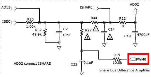
    Finally, I can't clearly understand the function of the "PWM0" in the following figure, Whether it used in Synchronous Startup mode or having other effects? 

    Looking forward to your reply, thank you very much!

  • 1, yes, you need to cut the PCB trace, also you need to modify the code.

    2, no hardware change, but you need to modify the code

    3, Synchronous Startup means start up 2 converters at the same time. You can use GPIO to do some kind of "hand shaking" such that they can start up at the same time. It is not difficult to implement this function by your self. We do not have more document on this.

    4,  PWM0 can be used to compensate the sensed current signal. It is not used in this EVM.

    Regards,

    Bosheng

  • I really appreciate your help and patient advice!  

    Thank you!