This thread has been locked.

If you have a related question, please click the "Ask a related question" button in the top right corner. The newly created question will be automatically linked to this question.

UCD9246: Intermittent PMBus

Part Number: UCD9246
Other Parts Discussed in Thread: UCD9240

Hello,

One of our customers is experiencing the following problem. Any troubleshooting steps are appreciated! Let me know if you need more info:

" We use two UCD9246 with each chip controlling one voltage rail with 6 phases, both are on the same PMBUS.  In the beginning, we configured the parts using TI tool to program the sequencer. The PMBus are exported to a microcontroller and used by the firmware.

During the first time power up, the firmware will use the TI scripts to configure the UCD9246 parts using PMBus commands.  Before sending the commands to the chips, both chips will have power enabled, and reset signal released.  Probing with scope verified that the power and reset signal are working as expected.

All sensor read to the chips are suspended until after the chips are configured via firmware.

We are having two issues when trying to configure the parts:

  • The chips would fail to communicate via PMBUS (NACK to PMBUS commands) intermittently.

There are occasions when the communications would work right away after reboot, but sometimes it required 3-4 power cycles before the parts responded to the PMBus commands with ACK.

When the chip failed to communicate, sometimes it ACKed on the first few commands, then NACKed on the rest.


  • The first command we are trying to send to the parts is PHASE_INFO. This command always got NACK from the parts.

If I add another PMBUS command before sending PHASE_INFO, then it would get ACK ok.  Which tells us the chip is operational.

If I add a soft-reset command is issued before the first PHASE_INFO command, all communications ACK successfully.  However I would assume soft-reset should not be a requirement here.

Could you please give me some suggestion on our observations and any steps to debug these issues?"

Thank you,
Ryan B.

  • 1)  It sounds like they are actively switching the RESET pin on the controller and that they are releasing it after power has been applied to the controller.

    The RESET pin is there to control the initialization of the part but really isn't meant for active control by the system/user, especially for shutdown control. If they are actively controlling the release of the RESET then I would make sure that this is a clean monotonic release but I would prefer that it is just connected to VIN with an RC as shown in the datasheets.  The PMBus_CNTRL pin or the OPERATION command should be used to provide dedicated power-up/down control for the system.

    Also how long is the time period between releasing the RESET pin and first communication attempt with the controller?

    As I recall it takes about 20ms nominally to initialize the controller (I can't remember and I'd need to check if there are any instances where the initialization would require additional time, I know some of the UCD sequencers do but I don't think that applies to the UCD controllers).

    2)  The PMBus interface from the microcontroller.

    How does the microcontroller implement the PMBus interface, is it a bit bang I2C interface or a complete SMBus compatible HW interface?

    Is it capable of handling clock stretching by the UCD9246?

    Have they captured any PMBus communication when the NACKing has occurred?

    What value of resistor pull-ups are on the clock and data lines?

    How far is the microcontroller from the UCD controllers, is one controller more susceptible than the other to NACKing?

    Are the host and slaves on the same ground plane?

    Are there multiple hosts on the bus, i.e. can two microcontrollers control the bus at the same time or do they have the Fusion SW and USB-to-GPIO adapter connected and the host microcontroller connected at the same time?

    3)  Can you provide the schematic for the power system and the interface with the micro?

  • 4) Do the two UCD9246 have different addresses?
  • Hi Brad,

    Thank you for the very thorough response. See answers to your questions below.

    1. The RESET pin is not being controlled by the firmware, it is connected to a circuit similar to your suggestion.
      We are actively controlling the PMBus_CNTRL pin to power up/down the system.

    2. Between powering up and first communication attempt, there is a 300ms delay

    3. It is a complete SMBus compatible HW interface.

    4. Yes, the microcontroller is capable of handling clock stretching.

    5. I have captured the communication via a logic analyzer, as well as via serial prints. There were not any abnormalities when NACK occurred.

    6. The pull-ups on the clock and data lines are 20k 

    7. Both controllers are equally susceptible to NACKing. I have tried changing the order in which the controller is being programmed, the results are similar.

    8. Yes, host and slaves are on the same ground plane.

    9. There is only one host microcontroller on the bus. There is an isolator that we use to isolate the microcontroller when using Fusion SW, and vice versa.

    10. The devices have different PMBus addresses.

    Thank you,
    Ryan B.

  • Schematic appears to have nRESET (pin 9) tied between the two controllers, is this true?

    I would try separating these two pins to see if this elevates the issue.

  • Something else to look at, slew rate of 3.3V on the controller, there is a spec for a minimum slew rate of 0.25V/ms between Vreset min and 2.9V.
  • Hi Brad,

    The customer measured the slew rate at pin 45 V33D and found it to be .88V/ms between 2.4V and 2.9V. Should be good on that front.

    Regarding the resets, they are tied together. Can you elaborate on how this might cause a problem?

    Thank you!

    Regards,
    Ryan B.
  • Actually, it may not be that they are tied together. What are they tied to? I know you mentioned that they connected to a "similar" circuit.
    What is the slew rate on the RESET pins, because I believe the slew rate spec on the 3V3 may have related to the RESET pin as it is normally pulled up to that rail.
  • On the reset pin, the voltage rises from 2.4 to 2.9 within 44ns.

    Should we try slowing this down to the .25V/ms minimum as required by the 3.3V rail?

    -Ryan B.
  • Wow, I don't know of any UCD applications with that fast a transition on the RESET pin, as most users just connect the pull-up to the 3V3.

    Probably worth trying to slow that slew rate down a little closer to the minimum and see if it clears up the situation.

  • Hi Brad,

    While we wait for the EE's at this customer to make changes and re-test based on your recommendations, they had a few other questions/points we wanted to get your insight on:

    • We are configuring one controller at a time. I observe that there are times when the first controller gets configured successfully, the second one still fails.
    From my understanding, the two are very similar, they both shared power, nRESET, and communication bus. What would cause one to fail and the other to succeed?

    • When using Fusion to configure the controllers, they both get configured correctly.
    When using that method, the controller’s buses are disconnected from the CPU, and connected to the programmer.
    The nRESET signal would behave the same with when using the CPU, the power to the board should also be similar. The PMbus sequence should be the same.
    Is there any extra step Fusion is taking beside the PMUS sequence?

    Thank you!

    Regards,
    Ryan Bishop
  • Difference between micro vs. Fusion write:  Likely to be a larger time delay between when the board power is applied and the configuration write is initiated when using the Fusion GUI.

    One possibility:  The script that is exported from the Fusion GUI includes several commands followed by a pause which place the controller in the off state to allow the configuration to be written (some commands cannot be written while the part is operating, PHASE_INFO is one of them).  Went back to first post and noticed that it said that PHASE_INFO is the first command being written.  If this is the case then they have removed the steps that insure the part is disabled (these steps can be skipped if they only ever plan to configure a new device or they can guarantee operation is disabled prior to configuration but if they are attempting to rewrite to a device that is configured and operational then it will NACK that command).

    Another:  The script includes STORE_DEFAULT_ALL after several of the first level commands (such as PHASE_INFO) are written to setup registers for remaining configuration data.  This is followed by a 2 sec pause then a SOFT_RESET and another 2 sec pause, the SOFT_RESET and second 2 sec pause are probably not needed as I believe these were included to insure some of the earlier versions (UCD9240) came up properly during configuration.  Is it possible that they are attempting to write before the device has recovered from the write (STORE_DEFAULT_ALL)?

    Can they provide their script?

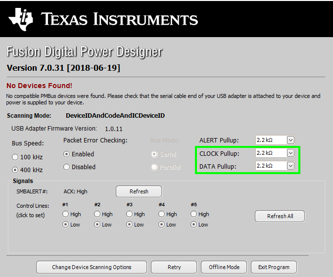
    Another thought:  When they are connected to Fusion they are using the USB-to-GPIO adapter, there are four options for pull-ups of the clock and data lines internal to the adapter, open drain, 668 ohm, 1.1k ohm and 2.2k ohm.  To find out how the customer's adapter is set, open the Online version of the GUI with the adapter plugged into the host but leave the 0 pin ribbon cable disconnected.  The following screen will appear when no devices are detected.

    Are the PMBus connections from the micro similar?

  • Hi Brad,

    I'd like to thank you for all your help troubleshooting this issue. The customer was able to find the root of the problem:

    "We found and fixed the issue with programming the chips.
    The script from FUSION had a delay of 1000ms after STORE_DEFAULT_ALL instead of 2000 ms. "

    You were amazingly helpful.

    Regards,
    Ryan B.