This thread has been locked.

If you have a related question, please click the "Ask a related question" button in the top right corner. The newly created question will be automatically linked to this question.

UCD9246: Proper Reset Process

Part Number: UCD9246

Hello,

We are experiencing the below issue:

  • After the chips are configured, tried to turn on the voltage rails by writing OPERATION_ON and pull pin PMBUS_CTL high. The rails remain low.
  • Checking the status registers, I got:
  • STATUS_MFR_SPECIFIC: 0x80
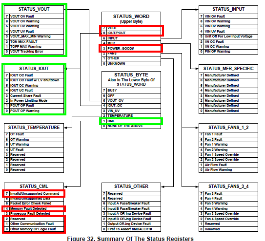
  • STATUS_WORD: 0x00c8
  • STATUS_CML: 0x97
  • Sending SOFTRESET does not help with the issue.

Could you please help me with these questions?

  • Do the chips require an nRESET pulse to properly reset and start outputting?
  • If not, would doing so have any negative effect?
  • If a hard reset via nRESET is not viable, is there any timing constrain I need to follow to properly reset and start the chip?

Thank you,
Ryan B.

  • Best option moving forward is to provide the configuration file for the UCD9246 and the power schematic.  nRESET should be tied to 3V3 by resistor 10K pull-up, including a 10nF capacitor wouldn't hurt either.  Prefer nRESET is not actively used to control power circuit, PMBus_CTRL pin or OPERATION command to enable/disable rails.  Some customers like to include the ability to cycle this pin as a last ditch option but it has never been shown to be needed.

    1) STATUS_MFR_SPECIFIC: 0x80

    This is a CLF (Current Limit Flag) which is triggered by the internal overcurrent comparator (vs. FLT which is often an OC triggered by the driver circuitry).  It is a paged fault so it would be specific to a particular rail.  Probable older logged fault as MFR bit in STATUS_WORD not set.

    2) STATUS_WORD: 0x00c8

    Multiple items - Can be Error or Current State (sent Little Endian so bytes need to be reversed to 0xc800)

    VOUT (There should be corresponding STATUS_VOUT register value that provides additional info)

    IOUT (There should be corresponding STATUS_IOUT register value that provides additional info)  Likely bit 7 (IOUT_OC_FAULT)

    POWER_GOOD# - Rail is OFF

    3) STATUS_CML: 0x97

    A few items here shown below, appear to be old logged faults as the CML bit is not set in the STATUS_WORD.  Likely from attempting to write while part is initializing or shutting down.

  • Hi Brad,

    From your response, I take that using nRESET would not cause any problem, but it should not be needed to control the devices. Is this interpretation correct?

    Furthermore, the main problem that I am having is that the voltage rails on the devices fail to turn on. These are what I observed:

    • When I follow this sequence: Configure Dev1 > Soft Reset Dev1 > 2sec delay > Configure Dev2 > Soft Reset Dev2 > PMBus_CTRL pin ON, and OPERATION command ON, the rail on Dev2 turns on OK.
    • When I follow this sequence: Configure Dev1 > Configure Dev2 > Soft Reset Dev1 > Soft Reset Dev2 > 2sec delay > PMBus_CTRL pin ON, and OPERATION command ON, both both devices fail to turn on.
    • When the rails failed to turn on, I attempted toggling PMBus_CTRL pin, and OPERATION command two more times, without any luck.
    • I tried sending CLEAR_FAULT before PMBus_CTRL pin ON, and OPERATION command ON, still not any luck.

    These are the questions I have:

    1. Does this mean that there is some timing constrains between the time the configuration is complete and the rails to be able to turn on?
    2. Is the soft reset required to turn on the rails?

    Regards,

    Ryan B.

  • Hi Brad,
    Just wanted to check in for any updates.
    Thank you!
    Ryan B.
  • Exercising nRESET shouldn't cause any problems but there should be no need to use it during normal operation (power conversion) of the device.

    As for programming, the PMBus script that can be exported from the Fusion Digital Power Designer contains all the operations needed to properly configure a device. The Soft Reset should only be needed after completing the base configuration commands, PHASE_INFO, GPIO_SEQ_CONFIG, FREQ_SWITCH (each rail) and SYNC_OFFSET have been written followed by a STORE_DEFAULT_ALL command, as these are required to define which rails/phases are to be used. There should be a delay after this STORE_DEFAULT_ALL before the SOFT_ RESET to allow the device to complete the update of the flash memory. Then another delay for the device to re-initialize after the SOFT_RESET before continuing on with the rest of the configuration commands and the final STORE_DEFAULT_ALL required to store these configuration commands to the flash memory. Another SOFT_RESET can be applied after the flash completes the write process but should not be needed. If the SOFT_RESET is applied before the write process finishes then the config flash data would be corrupted and it would not have a valid checksum so I believe the device reverts to the default configuration. Is it possible this is occurring?

    Do they have a copy of the Configuration Programming for UCD Devices document?

    /cfs-file/__key/communityserver-discussions-components-files/196/6102.1007.Configuration-Programming-of-UCD-Devices.pdf

  • Link should work now.
  • Thank you so much for the feedback.
    Is it possible for you guys to help me take a look at the sequence that we are using to see if there is anything amiss?

    I have sent you the PMBus scripts that were generated by Fusion, as well as the modified scripts that I am using.

    We are using this sequence to configure and turn on the voltage rails:
    1. Configure device 1 using script
    2. Configure device 2 using script
    3. Enable device 1, device 2 using PMBUS_CTRL pin
    4. Send PMBUS command to turn on device 1, device 2

    Currently with this sequence, the rails are not turning on after step 4.
    If we insert a step to toggle nRESET line after step 3, both devices output correctly on the rails.
  • The modified script provided by the customer diverges from the method generated by the FUSION GUI after the first four commands have been loaded, specifically in the area I specified from the Aug. 9th post. I would focus on correcting this and see if the issue is resolved. Also, the script provided is not their actual code which may differ further from the original script.
  • They should be able to just stick with the script order as generated from the Fusion GUI.

    As for failing with the default script, the only thing I can think of is that the V33 voltage rise on the controller may too slow, possibly resulting in the NACK of commands.  There is a minimum spec for V33 slew rate of 0.25 V/us.

    But even this would not explain away the fact that the modified script "works".

    If they were using a hard reset on the nRESET pin then maybe the above would be the solution but the modified script uses the SOFT_RESET command.

    Makes no sense to me why the controller would except the first command (SOFT_RESET) from the modified script but not the first command (PHASE_INFO) from the default script.

    As for needing the extra SOFT_RESET after completing the configuration, I was able to locate a UCD9246 eval board and will attempt to verify the operational requirements needed after the configuration completes.

  • Hi Brad,

    Thank you so much for the insight. I will pass this info along.

    Please do let me know how things go when you try to replicate this issue on the EVM.

    Regards,
    Ryan B.
  • Hi Brad,
    Did you get a chance to run those same scripts on your EVM? Any findings?
    Regards,
    Ryan B.