This thread has been locked.

If you have a related question, please click the "Ask a related question" button in the top right corner. The newly created question will be automatically linked to this question.

REF5040: Questions about REF5040

Part Number: REF5040
Other Parts Discussed in Thread: REF5025

Dear,

We use REF5040 in PT100 temperature detection circuit, now there some questions to be explained:

1. We find that it needs about 30 sec from turn-on to stabilization, is it normal?

2. The max value of output voltage is 4.08V by oscilloscope, the error is about 0.4%, greater than 0.1%, can you explain it?

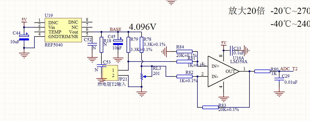
3. We use REF5040 in PT100 temperature detection circuit, can you verify that if the schematic as follows is correct?

  • Hi user4699596

    1) REF5025 start up time with 10uF output capacitor is around 1.5ms. Please refer to figure.15 of datasheet for more details. For REF5040 we expect it to be around 2ms. REF5040 output should settle to 0.1% of FS value within this time.

    Turn on settling time of 30 Sec looks very odd. Can you please check what is the input supply start up time. Are you using any capacitor on NR/TRIM pin. Can you share start up waveforms for input supply and REF5040 output

    2) I recommend to measure this value with 6 and 1/2 digit multimeter. Else you can either increase number of average on scope settings.

    Apart from intial accuracy specification, voltage reference output can change due to solder shift effect, temp drift effect, board stress. Please make sure you are following solder profile mentioned in Section 8.1 of REF50xx datasheet to keep these errors low.

    3) schematic looks ok. I believe RL3201 corresponds to PT100 sensor in your schematic

    Thanks & Regards

    Abhijeet Godbole

  • Dear Abhijeet,
    Thank you for your reply, I will test it as you say. Thank you again.
  • hi Abhijeet Godbole
    a REF5040 has been used in my design to provide a voltage reference,
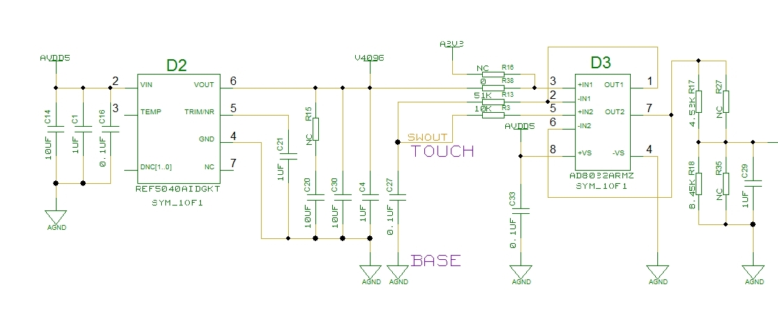
    here is a confusing situation, the Vin of REF5040 is 5.0V, the Vo of REF5040 is 5.0V(should be 4.096V, however, 5.0V with or without load circuits), but the result of the ADC is correct.
    plz give me some advise.
  • Hi user4551715,

    Can you provide us a schematic or anymore data for us to better assist you?

    -MZ
  • part of the schematic, the Vout of REF5040 has not been used at other part of the schematic, wish u give me some advise

  • The circuit looks good to me. Can you provide us scope shots of the VIN and VOUT pins during start up? Also try removing R38 and check if the issue persists.