This thread has been locked.

If you have a related question, please click the "Ask a related question" button in the top right corner. The newly created question will be automatically linked to this question.

BQ34Z100-G1: Sudden Jump in Remaining Capacity

Part Number: BQ34Z100-G1
Other Parts Discussed in Thread: BQEVSW, BQSTUDIO

We just went into production with a fuel gauge board that uses the bq34z100-G1 chip.  The battery we are pairing the fuel gauge with is a 7.5 Ah 4S LiFePO4 pack.

The first batch that we built was 9 batteries.  Our procedure is to program, calibrate, and test the fuel gauge boards, then pair them with the battery packs.  The packs get fully cycled twice and then we retest the fuel gauge boards in a fully discharged state.  All batteries passed and they were sealed up into their final housings (no longer can read ant info from the fuel gauge IC).  The batteries are then charged to just under 30% before they move from production to stock/shipping.  The batteries sat for several days but the next time they were checked the SOC had jumped to above 50%.  This happened on 8 of the 9 batteries.  Unfortunately theses packs with their gauges are fully sealed and i can not read any detailed information from the bq34z100-G1.

I have since brought through a larger batch of 20 fuel gauge boards.  Some boards have demonstrated the same jump, from 27-30% to 50-60%.  I have not been able to construct the circumstances under which this jump will always occur and have not been able to collect logged data on a battery capturing the jump or transition.  I have confirmed that it is the remaining capacity that jumps while the FCC stays virtually the same.

Under what circumstances can Remaining Capacity jump while the pack is relaxing?  I should note that sometimes the jump happens almost immediately after coming off of the 30% charge and sometimes it has taken 1-2 days.  The inconsistency of the problem has made it especially difficult to narrow down or capture.

What information would help in diagnosing the underlying problem.

Thanks,

Matt

  • Hi Matt,
    Did you set your LFP relax flag? Do you have smoothing enabled? What is the status of the relax jump ok and relax smooth ok flags?

    You will need to have gain access to one of your packs and try to get log data showing this behavior and a gg file for analysis.

    thanks
    Onyx
  • Hi Onyx,

    The LFP relax flag is set.  Smoothing is enabled.  Both RELAX_JUMP_OK and RELAX_SMOOTH_OK are enabled.

    I will potentially have an easier time getting gg files before and after, but getting logged data of the jump happening has been very difficult due to the inconsistency of whether or not it occurs and the exact timing.

    For most packs, Qmax did not seem to be updating during the two complete cycles.  Could this be an indication of a bad golden image learning?  Could that lead to or at the very least play a role in these types of jumps?

    I've created a new golden image with a heavily learned fuel gauge and have begun to bring through 5 packs with this new golden image to see if the issue persists.

    Thanks,

    Matt

  • Hi Matt,
    It is possible temperature changes occur and rem cap simulation occured. Try successfully reproducing the issue and then disable both the relax jump ok and relax smooth_ok... This will hold the SOC at 30%

    thanks
    Onyx
  • Hi Onyx,

    I successfully logged the jump occurring.  It appears that the Remaining Capacity jumps when OCV measurement takes place and again with each subsequent update to DOD0.  Not sure why it is taking 48hrs plus to do an OCV measurement once in RELAX mode.  I have confirmed on separate batteries that disabling both the RELAX_JUMP_OK and RELAX_SMOOTH_OK prevents Remaining Capacity from jumping, although True Remaining Capacity still jumps in the same manner.

    I've attached the data for your review. Would this behavior indicate that our stored DOD(OCV,T) table is way off for our battery chemistry?

    Thanks,

    MattFG0060 No PIC 30 Pct Relax 3rd Night.log

  • Hi Matt,
    These jumps are inevitable because the gauge performs rem cap simulations in relax mode. Because you are using LFP cells, it takes a while for the cells to relax especially after charge hence the gauge waiting for a long time (48hours) before the OCV is taken. The LFP relax flag controlls this.

    so because the cells voltages relaxes higher, when the gauge performs simulations at the different votlages you will get different rem cap results.

    thanks
    Onyx
  • Hi Onyx,

    I understand the LFP cells can take a little longer to relax, but not to this degree and the voltage and temperature were not still moving.  It seems like there is something else going on.  I picked out some data points that help demonstrate this.

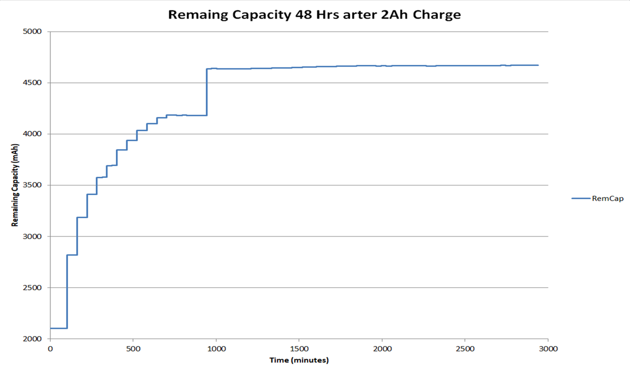
    Time (minutes) RemCap FullChgCap Voltage Temperature TrueRC TrueFCC DOD0Time
    20 Hrs Earlier 2090 7290 13208 24.8 2307 7507 442
    0 2104 7290 13208 24.3 2322 7507 765
    100 2105 7290 13204 24.9 2324 7507 792
    101 2820 7343 13204 24.9 2820 7343 0
    161 3185 7341 13204 24.6 3185 7341 0
    221 3411 7334 13204 24.5 3411 7334 0
    281 3577 7332 13204 24.3 3577 7332 0
    341 3692 7328 13204 24.2 3692 7328 0
    642 4157 7313 13204 23.4 4157 7313 0
    942 4180 7303 13204 22.8 4638 7297 0
    1544 4652 7302 13200 23 4652 7302 0
    2145 4665 7306 13200 23.1 4665 7306 0
    2746 4669 7300 13196 22.9 4669 7300 0
    2 weeks later 4696 7215 13184 22.1 4696 7215 0

    You can see that when I collected data the night before the voltage and temperature were virtually identical and remains essentially the same throughout the collection. 

    And here is a graph of the Remaining Capacity over Time showing the nature of the pattern of the jumps:

    It seems like the gauge has no idea what the remaining capacity should be at a fully relaxed voltage and temperature.  Would this indicate bad learning or an incorrect Data Flash constant somewhere?

    Is there an up to date Application Report on how the gauge handles the Fuel Gauging Algorithm and any documentation on how this is adjusted when configured for LFP cells?  A year or two ago it seemed like the best document that described how the Impedance Track algorithm worked was SLUA450 from 2008.

    Thanks,

    Matt

  • hi Matt,
    The flatness of the voltage profile of LFP cells make it difficult for for rem cap simulation during relax. can you confirm if you have the DODWT flag set or clear? That document you pointed out is the IT detailed description we have.

    thanks
    Onyx
  • Hi Onyx,

    I can confirm the DoDWT flag is set.

    I guess my major hangup is I understand that the voltage profile of LFP cells is very flat which would make it difficult to run remaining capacity simulations in relax based purely on Voltage and Temperature and stored resistance data. 

    What does not seem right is that the gauge consistently thinks that a 27-28% SOC battery is actually 55-66% SOC.  If our raw pack is charged to that level (which is consistently 13.20V +/-0.01V) and then paired with the gauge it will think the pack is 65% SOC.  It would seem that the gauge should be able to make a good guess, albeit with a large error due to the flatness of the voltage curve, but its guess/simulation just seems consistently and significantly wrong in a specific direction.

    Maybe none of this really matters if the LFPRelax, DoDWT,  and SMOOTH flags are set and the RELAX_JUMP_OK and RELAX_SMOOTH_OK flags are cleared since the RMC and FCC will just base and update themselves on passed charge, but the degree/magnitude to which these other values are off makes me concerned there is something else that is not set or learned correctly.

    Thanks,

    Matt

  • Hi Matt,
    Did you check what the flat region of your chem id is and if those voltages are within the flat region?

    thank
    Onyx
  • Hi Onyx,

    I can confirm that when fully relaxed the battery voltages in this region are extremely flat.  For our 4s pack there is a 0.03V difference between 30% charge and 60% charge.

    Could you please confirm that for an LFP pack that we want the LFPRelax, DoDWT,  and SMOOTH flags set and the RELAX_JUMP_OK and RELAX_SMOOTH_OK flags cleared?

    Are there any other relevant flags we should be aware of for our LiFePO4 application.  Would it be helpful to attach a gg file of our current configuration?

    Thanks,

    Matt

  • Our chem ids have a flat region which is listed in the excel sheet when you download the chem updater for bqstudio or bqEVSW. what is the flat region for your chem id?
    thanks
    Onyx
  • Hi Onyx,

    I believe this is what you are referring to:

    Description Chemical ID Vqdis_min Vqdis_max SOC_min, % SOC_max, % Rhf,mOhm Rhf_lo Rhf_hi Qmax Ra0_charge
    LiFePO4/carbon 457 3277 3330 34 96 8 -31 31 80523 50

    So for our 4s pack, that would mean that OCV measurements should not be occurring between 13.108V and 13.320V?  The jump I collected data had occurred when the OCVTAKEN flag became set (indicating OCV measurements occurring) while the pack was at 13.204V at 24.9 degrees C. 

    Please let me know if any other information would be helpful.

    Thanks,

    Matt

  • Hi Onyx,

    Just wanted to make sure you saw my last reply.  Looking forward to your response.

    Thanks,

    Matt

  • Hi Matt,

    Yes, you're correct.

    With a per cell disqualified range from 3277 V to 3330 V, the disqualified range for your 4S pack will include voltages between 13.108 V and 13.320 V. The gauge will still take readings and log those values, but will not learn in that region.

    Please perform learning outside of the disqualified voltage range.

    If the above answers your question, please click on "This Resolved my Issue" button to benefit others who have the same issue.

    Sincerely,
    Bryan Kahler