This thread has been locked.

If you have a related question, please click the "Ask a related question" button in the top right corner. The newly created question will be automatically linked to this question.

LM5085: switch frequency stability of LM5085 DC/DC

Part Number: LM5085
Other Parts Discussed in Thread: TINA-TI

Hi everyone,

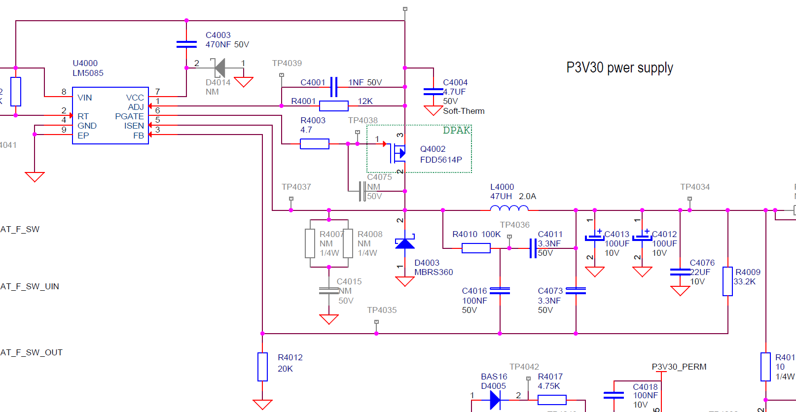
I am currently using the LM5085 DC/DC converter in order to convert 28V to 3,3V output :

We would like to improve the switching frequency thanks to the Rt resistance (R4002 in the schematic) and in the same time we would like to keep a good stability of the switching frequency.

I tried to change the switching frequency (resp 600kHz and 800kHz) but more it is big more the circuit is not stable ...

In the same time, I calculate the adjustement ripple circuit (R4010 + C4011 + C4016) thanks to this document : Transient response versus ripple - an analysis of ripple injection techniques used in hysteretic controllers, especially for the 600 kHz switching frequency, but the LM5085 seems to be unsteable.( We chose 100 mV output ripple for our application.)

Do you know if this integrated circuit has some metastability criteria above 400 kHz switching ?

Do you know some tips to fix Fsw ?

I would be grateful if you could answer this question as best as possible,

Kind regards,

Olivier D.

  • Hi Olivier,

    Would you be able to share your schematic again?  I am unable to see your image.

    Thank you,

    Katelyn

  • Hi katelyn,

    Thanks for your answer. I put the schematic in attachement :

    Can you see the image ?

    Regards,

    Olivier D.

  • Hi Olivier,

    Yes, I can see the schematic now. Thank you for sharing again.

    My recommendation is to start with the Quickstart calculator on the product folder. As you change the switching frequency, the passive components in the applications circuit will need to change accordingly.

    What is your input voltage range adn output current range? I will also simulate the design with the calculator if you can share this information.

    Thank you,
    Katelyn Wiggenhorn
  • Hi Katelyn,

    Thanks a lot for your answer ! In fact the problem is the following : Our customer wants the CISPR25 class 5 standard and we have problems in radiated emission. I've recently opened a new topic on the forum where I describe the question with a better accuracy :

    One idea is to increase the switching frequency of the LM5085 thanks to the Rt resistance.

    I noticed that if I put 600kHz instead of 400kHz (our default value) the radiated spectrum seemed to be less big.

    The problem is when I measure switching frequency just before the inductance, I see a very troubled signal with a variant Fsw.

    We designed an EMC input filter from the voltage supply line :

    We have chosen a pi filter which filters the 28V input voltage. Our requirements are the following :

    - Input voltage : 18V to 32V dc

    - output current : 1,4 A max

    - output ripple : 100mV (but can be changed if necessary)

    The problem is that we can not route the PCB again.

    Finally, I downloaded the TINA-TI software and I tried to simulate the FFT response at the output node but I didn't manage to obtain the correct spectrum.

    Thanks again for your future response,

    regards,

    Olivier D.

  • Hello Olivier,

    By changing the switching frequency, you will need to re-verify the passive components for stability (COMP, output inductor, COUT).

    What frequency spectrum are you failing the CISPR limits in? Is it the emissions due to the switching (FSW, harmonics of the switching frequency)? Is the switch node waveform clean - is there ringing on the switch node waveform?

    You can also try increasing the values of C4000, C4005, C4007 and C4008 to see if this improves the performance.

    Also, where are the self-resonant frequencies L4001 and L4003?

    Thank you,
    Katelyn Wiggenhorn
  • Hello Katelyn,

    We have problems especially in low frequencies, with switching harmonics (400k, 800, 1,2M, 1,6M ...)

    You are right when you say that increasing Fsw obliges to check thermal and consumption performances again, and it could be bad for our application !

    We have chosen several options to reduce harmonics :

    - put a shielded self with the same inductance value (47µH);

    - put a shielded hood above the Dc Dc converter area in order to limit radiated emissions;

    - try to slow down commutation signal of the MOSFET transistor thanks to a gate/drain capacitor, but we don't know exactly how choosing a good value.

    What do you think about these ideas ?

    Regards,

    Olivier D.

  • Hi Olivier,

    Using a shielded inductor as well as the shielded hood should definitely help.

    If you are having trouble at the switching frequency and its harmonic, I recommend focusing on the input filter components. The input filter is critical to filtering out the switching frequency. I would go through your filter components and recalculate to make sure you have optimized these values: www.ti.com/.../snva489c.pdf

    I would start with changing L4001 and L4003 to inductors within the range of 1uH - 10uH. Then calculate the necessary capacitance, and also calculate the necessary ESR for your electrolytic capacitors.

    Best Regards,
    Katelyn
  • Hi Olivier,

    Due to inactivity I am going to close this thread. Please feel free to post again on E2E if you have any additional questions.

    Best Regards,
    Katelyn