This thread has been locked.

If you have a related question, please click the "Ask a related question" button in the top right corner. The newly created question will be automatically linked to this question.

BQ25890: Why VSYS is only 1.87V with a 4.7Om load?

Part Number: BQ25890
Other Parts Discussed in Thread: , TEST2, EV2400, BQSTUDIO, BQ25892, TS3USB221

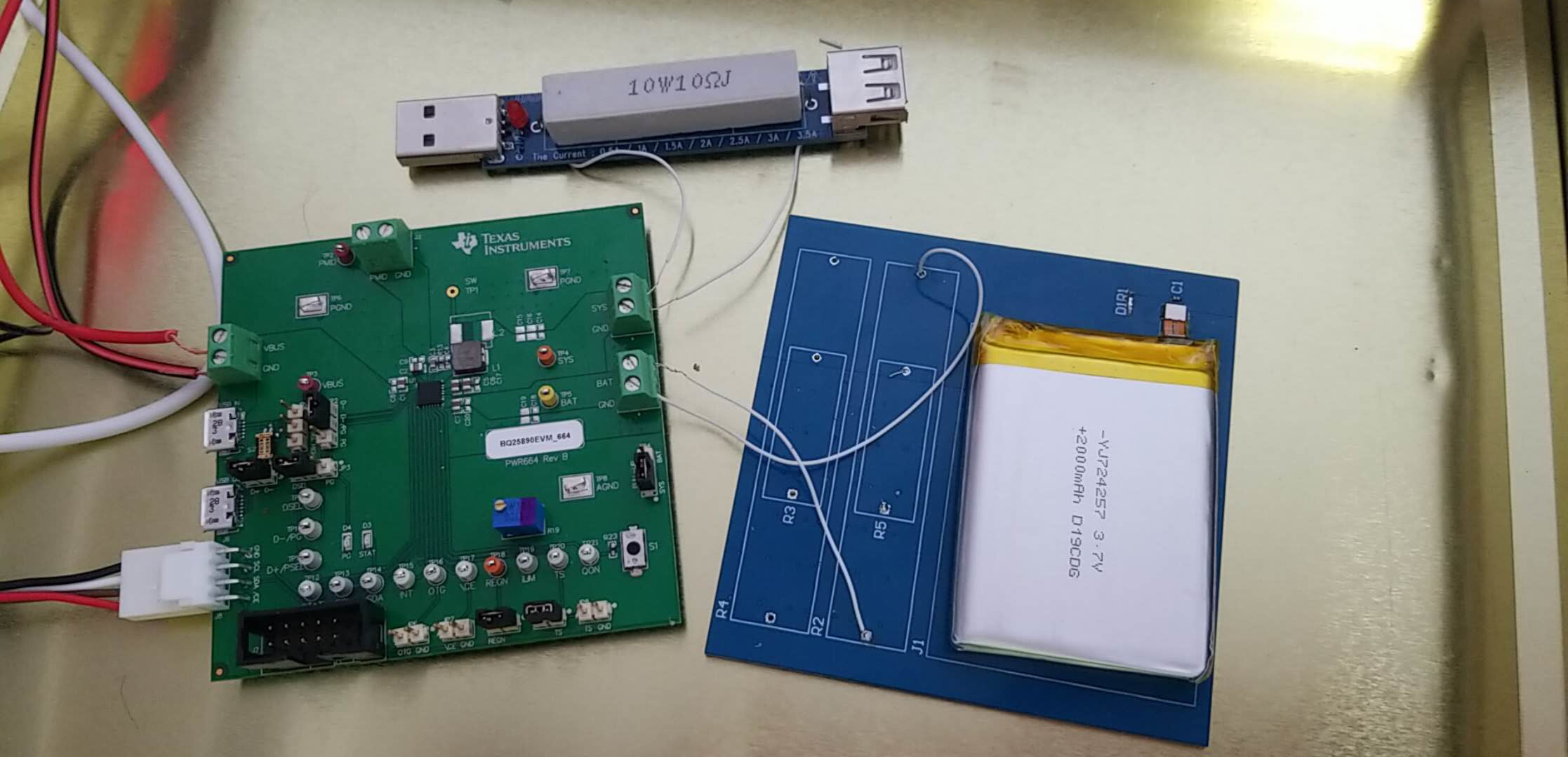
I use the schematic just as the BQ25890evm.

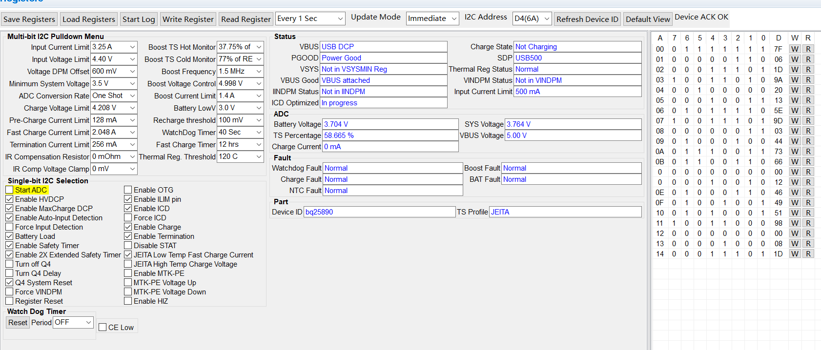
The system works well with battery. The Ilimit is 1.6A. And I did not program the chip through I2C.

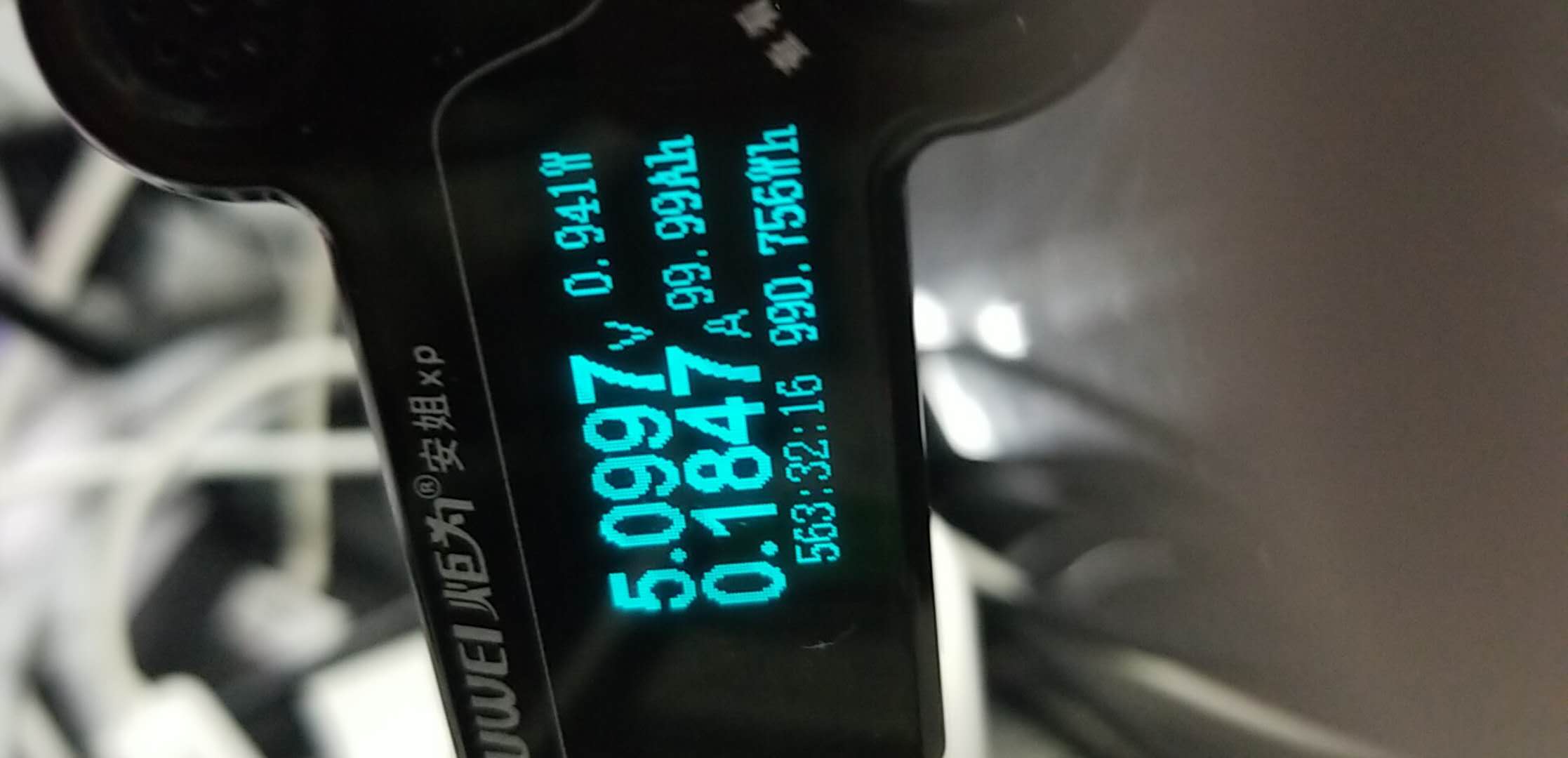
When I remove the battery and only connect the VBUS:

1. When the VSYS is connect to a 10Om load, the VSYS is 3.65V.

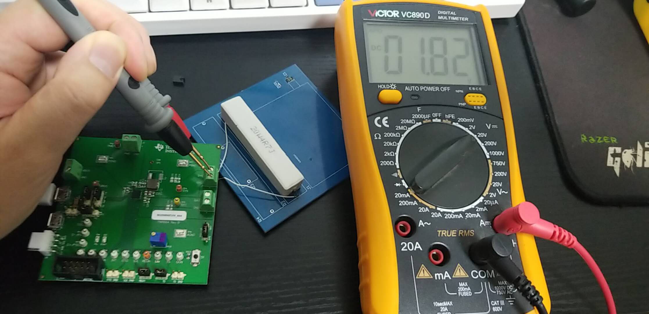
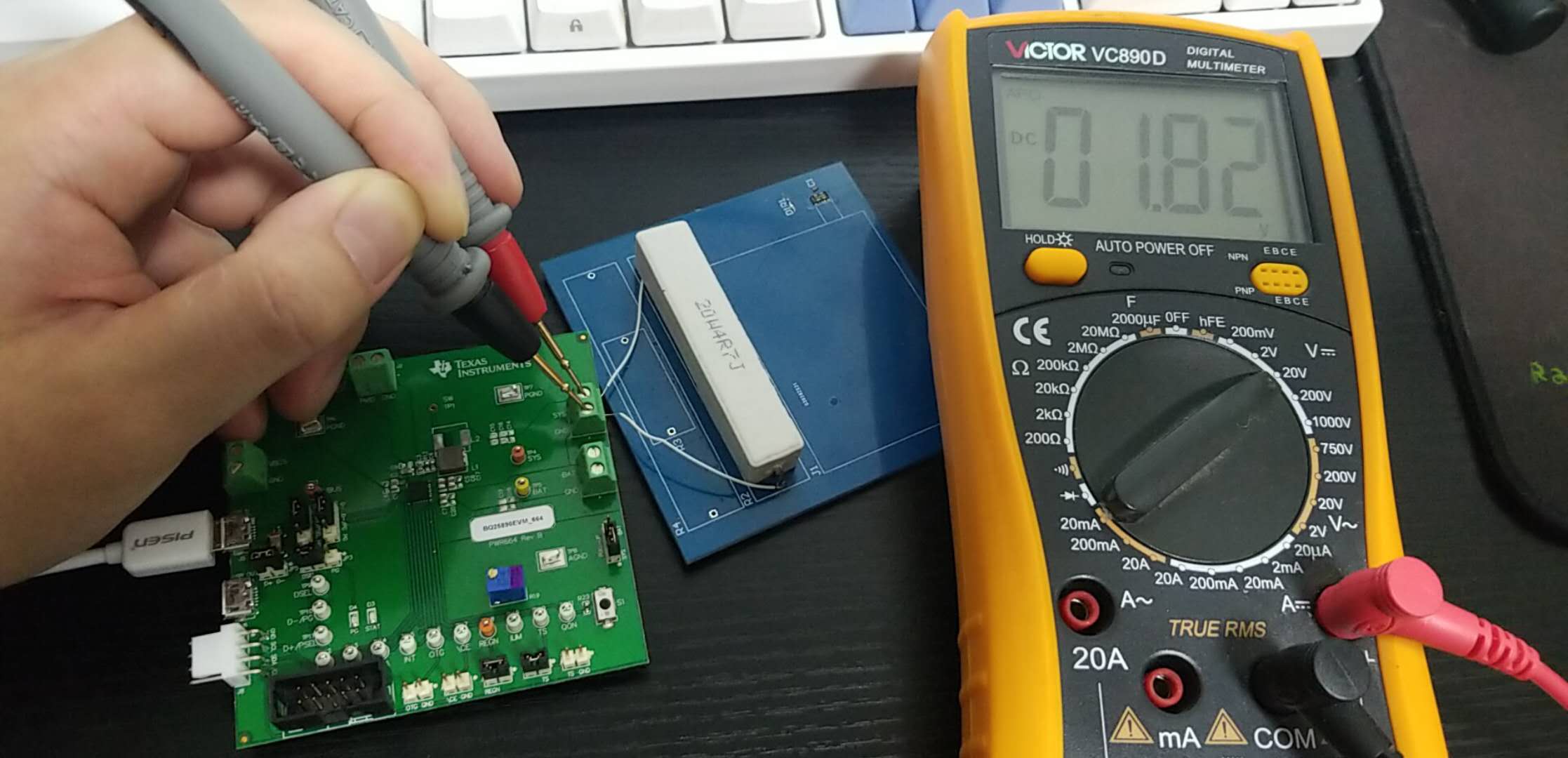
2. When the VSYS is connect to a 4.7Om load, the VSYS is only 1.87V.

Question: Is that normal? Why the VSYS drops below 3.5V (VSYS MIN)?

Question: What is the maximum current that VSYS can provide when battery is removed? I didn't find the value in the datasheet.

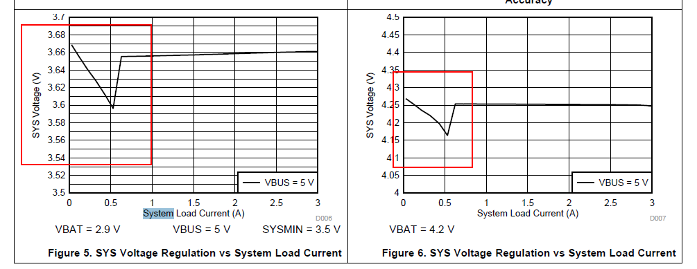
The Figure 5 and Figure 6 in the datasheet only show the SYS Voltage Regulation vs System Load Current when the battery is on.

Thank you.

Frank

  • Frank,

    Please try to power up the charger first without load. Connect the load after the system voltage reaches 3.65V. The charger soft start feature limits the input current to 200mA before the Vsys reaches 2.2V. More details can be found on the BQ25890 datasheet (version SLUSC86C) page 21.

    Regards,

    Eric
  • Hi Eric,

    Thank you very much for reply.
    Case1: VBUS is connected and Battery is connected

    Case2: VBUS is off and Battery is connected

    Case3: VBUS is connected and Battery is off

    Question 1: "The charger soft start feature limits the input current to 200mA before the Vsys reaches 2.2V" If that, the Vsys can not drive the 4.7Om load in all the three cases. But in fact, only in Case3, the Vsys gets 1.87V. And in the other 2 Cases, the Vsys gets about 3.6V and drive the load normally.

            So, I think the Page 21 is not related with the problem. Am I right?

    More description: In my application with my board, when WIFI disconnected, the board takes 250-300mA current with 5V supply. And when WIFI connected, the current consume increase to 350-400mA with 5V supply.

             In Case 3, the application works well when WIFI disconnected. But when connecting to WIFI, the DSP is reset, and with the oscilloscope I find the Vsys has a drop.

             In the above figure, the blue channel is Vsys and the yellow channel is 1.8V for DSP. When the board try to connect to WIFI, the current increase and the bq25890 cannot afford sufficient current, so the Vsys drops.

             In Case 1 and Case 2, the application works well both when WIFI disconnected and WIFI connected.

    Question 2: According to Figure 5 and Figure 6 in the datasheet. I think the 2 figures tell us that the Vsys can provide up to 3A current in Case 1 and Case 2. Am I right?

    Question 3: But the datasheet doesn't tell us the current limit in Case 3 or give any figure to describe that. What is the maximum current the Vsys can drive in Case 3?

         Thank you so much.

         B.R.

    Frank

  • Frank,

    In cases 1 and 2, a sufficiently charged battery can provide the SYS power.

    In case 3, the buck converter's output power is limited by the charger's input current limit.  During startup, the input current is limited to 200mA for soft start.  If the SYS voltage never reaches the SYS short circuit thershold, the input current limit stays at 200mA.  If the SYS voltage exceeds the SYS short circuit thershold, the input current limit is set to the LOWER of setting per D+/D- pin OR the ILIM pin setting.  For example, if D+/D- finds an SDP port, then the IINDPM register would be set to 500mA even if the ILIM pin resistors sets the input current to 3A.   You can disable the ILIM pin using the EN_LIM register.

  • Hi Jeff F,

        “More description: In my application with my board, when WIFI disconnected, the board takes 250-300mA current with 5V supply. And when WIFI connected, the current consume increase to 350-400mA with 5V supply.”

        The board is charged with a SDP USB port and the current is measured using a USB current meter. And the ILIM pin resist is 220Om, which means the ILIM pin current is 1.8A. The “ LOWER of setting per D+/D- pin OR the ILIM pin setting” is 500mA.

        In case 3, when my board is powered up, the WIFI is not connected by default, and the current is 250-300mA (>200mA), and the SYS voltage is 3.65V-3.7V. So I think it does not matter with the startup things described in page 21 in the datasheet. And when the software connet the WIFI, the current increased and the USB current meter showed the current increase to about 340mA and then drop back to 220mA. The current drop matches the SYS voltage drop in time.

       And in case 1 and case 2, when WIFI is connected, everything works normally.

       So, I think the SYS voltage drop does not matters with the ILIM. I think maybe in case 3, the bq25890 sys can only provide about 300mA current. But I didn't find any information about the maximum current in case 3. Can you help to confirm that and give the maximum current in case 3?

       The figure 5 and figure 6 shows the Current VS Voltage curve for case 1 and case 2. Not case 3.

       Thank you so much.

       B.R.

    Frank

  • Frank,

    It is a buck converter. If VBUS=5V and IINPDM=500mA then using efficiency power balance (eff=Po/Pin), SYS should be able to supply ISYS=5V*0.5A*0.90/3.65V =616mA. What is the voltage at charger VBUS pin? Is dropping due to high resistance connection to USB port or due to meter?
  • Hi Jeff,

    When WIFI is not connected, the current is 250-290mA, the VBUS voltage at VBUS pin is 4.97V.

    When connecting WIFI, VSYS drops, but the VBUS pin never drop.

    For test, when connect the VSYS with a 4.7 Om resist load, the VSYS is 1.65V, but the VBUS pin is 5.03V.

    Frank

  • Frank,


    Can you send the schematic for the bq25890, including inductor part number? Do you have a way to read the I2C registers when this is happening, including an ADC measurement? The status registers will tells us what is happening. If not, then can you send oscope plots of VBUS, SW and SYS when this occurs?
  • Hi Jeff,

         The schematic is below:

       The inductor I use is SPM3020T-2R2M-LR 

       And althrough the I2C is connected to DSP, but the DSP is reset when the SYS drops. I cannot get the register when this happens.

       This is the VSYS (blue) vs the SW (yellow) when this happens:

        This is the VSYS (blue) vs the VBUS (yellow) when this happens:


           Thank you so much!

    Frank

  • Frank,

    Can you zoom in on the SW pin when SYS drops out to show the squarish waveform like shown in d/s figure 54? Do you have a way to measure the charger's input current? I strongly suspect the charger is input current limited.
  • Hi Jeff,

         Thank you very much.

         The 2 figures below shows the SW (yellow) and SYS (blue).

         Figure 1, the WIFI is not connected. Figure2, the SYS drops when connecting to WIFI (I set the trigger level to 2.2V, falling edge). Since the SYS drops in several ms, you can see the SYS is a straight line in 100ns scope.

    Figure1:                     


    Figure2:

    The auto measurement in Figure1 is not acurate because of the over shot. The cursor measurement is:

                    VSYS                     Pos Width            Neg Width

    Figure1    3.7V                       528ns                   160ns

    Figure2    2.2V                       352ns                   336ns

    I use another 2A charger and use the USB current meter to monitor the current. When the battery is on, the current is 1.08A. So I don't think the problem is because of the input current limited.

       B.R.

    Frank


  • Frank,

    Can you remove the USB meter and short D+=D- and retry?
  • Hi Jeff,

         Thank you.

          I ordered a BQ25890EVM-664 from TI and today I got it.

          TEST1. I use a 4.7Om load for test.

          1. When no load is put at the VSYS, the VSYS is 4.2V. (D+ D- not shorted)

           2. Then, I put the load onto the SYS while keeping the board powered by the VSOURCE. The VSYS drops to 1.82V which is similar to the phenonmen that happened on my board (1.75V). Here now, the VSOURCE keeps on 5.08V and the current is 0.18A.


       3. I also repeat the above experiment with D+ D- shorted. The exactly same phenonmen happened, the VSYS droops to 1.82V.

      4. You can see that the Vsource did not drop. And the Vsource is a 2A charger and as I said, when the battery is put on, the meter shows the current is 1.08A.

          And I also tried the experiment without the meter. The exact phenonmen happened.

    5. If a 10Om load is used. The VSYS is 4.19V and everything is OK.

        So, I think the bq25890 VSYS can not provide > 4.2/4.7=893mA current when battery is off.

        Question1. What is the maximum current that the VSYS can provide when the battery is off?

        TEST2.  Compare my board with BQ25890EVM-644.

        Both the boards can not drive a 4.7Om load.

        When the load is 10Om, the VSYS on my board is 3.64V while the VSYS on EVM is 4.19V.

        Question2 : What is the difference between my board and EVM?

        Question3 : The STATE LED on my board blink once at a time, while the STATE LED on the EVM blinks much quickly. Why?


         B.R.

    Frank

  • Frank,

    I have used the bq25890 to provide well above 2A from 5V/3A input so I know it is capable. To summarize:
    1. At startup with SYS < ~2.0V, input current is limited to 200mA so the charger will not startup into 4.7ohm.
    2. After startup, the input current limit is clamped to the lower of the setting per the ILIM resistor or setting in the IINDPM register. With the 890, the IINDPM register is configured by D+/D- pins. With D+/D- shorted, IINDPM is 3A but, unless you disable ILIM resistor via I2C or also change resistor to set it to 3A, the ILIM resistor clamps the input current below 3A. If I recall correctly, the EVM ILIM resistor has a potentiometer in parallel with fixed resistor. If you increase the potentiometer to the maximum, so that help?
    3. If the load transient caused by quickly added such a large load causes the SYS voltage to drop <~ 2.0V, the charger could get confused and think it is in startup, which returns you to condition one above. In that case, you will need to add additional capacitor from SYS to GND that can absorb more of the transient and prevent such a droop.

    With the EVM, you can use the bqStudio I2C software to read the charger's status register, which might tell you the problem. Do you have an EV2300 or EV2400 I2C box to use with the software?
  • Hi Jeff,

        Thank you very much.

        I find that the JP10 is shorted with a jumper on the EVM, and the VSYS is 4.2V. Remove the jumper in JP10, the VSYS become 3.65V.

        In my test, the RLIM is 130Om on the EVM (the R19 potentiometer is set to 0Om). So the ILIM is 355/130=2.73A.

        In my test, the 4.7Om load is in parrel with a 1uF cap. With the 4.7Om load, the VSYS is 3.13V.

        And with the 10Om load, the VSYS is 3.65V, when I open the power first, and then connect the load to VSYS manually.


    With the 4.7 Om load:

    The adapter is recognized as a SDP, and the current limit is 500mA. 3.65/4.7*3.65/0.9/5=0.63A.0.5A. 

    That's why the VSYS drops. And if I set the current limit to 3.25A, the VSYS can be 3.65V even with the 4.7Om load.

    Thank you for your advice.

    But I still have some problem with the EVM:

    Problem1: With a 2A adapter and D+/D- shorted on the EVM board, the adapter is still recognized as a SDP. (current meter is not used). But on my board, I did the experiment many days ago and it's recognized as DCP.

    Problem2: With the battery on, the adapter never charges the battery. But with my board, the adapter charges the battery with 1.08A.

    For the above 2 problems, I've also tried other adapters, but always SDP and never charge.

    I have not found the reason from the registers, could you help. Thank you so much.


    B.R.


    Frank

  • Frank,

    First, please check the EVM to ensure that it has a bq25890 installed and not a bq25892.  Then, confirm that JP1 shunt is not installed and JP2 shunt is connected between pins 1 and 2.  If you are using a power supply, you can install the shunt on JP5 to short D+=D- and simulate a DCP.  If you are plugging in a DCP adapter, use J5.  If that doesn't work, try flipping the S2 switch.

  • Hi Jeff,

            I use a power supply, set 5V output and 2A current limit. The S2 is switched to the right position which makes D+ D- shorted. The battery and a 10Om load is connected to the VBAT and VSYS receptively. The Rlimit is adjusted to the smallest value 130Om, so the Ilimit set by the Rlimit is 335/130=2.577A.

    The connection is shown below:

    The Vsource is recognized as a DCP, and the regisiters are shown below:

    If the power supply is off, the VSYS is 3.7V which means the power now is supplied by the battery (VBATT is about 3.7V for this half full battery).

    Question 1: Why the Input Current limit is only 500mA?

    Question 2: Why the state is still not charging? The Isource shown in the power supply is 320mA, but if the battery is removed, the Isource is 297mA. So the power supply drives 20mA into the battery. I wait for 10 minutes, the Isoure is still 320mA and the state is still not charging.


    Then I change another battery and switch the power supply off and on. This battery is nearly full, the VBATT is about 4.124V as shown below,

    The state is still not charging, and the input current limit is still 500mA.

    But this time, the Isource is 370mA, which means about 70mA is driven into the battery. But the state is still not charging.

    Please help. Thank you.

    B.R.

    Frank

  • Please note that battery charging is enabled when CHG_CONFIG = 1 and CE pin = Low. CE pin must be Low to charge. Please install JP7 shunt: JP7 CE pin setting: pull low to enable the charge.

    The input current limit detection is correct because REG00[5:0]=3.25A (top-left corner on the GUI) for DCP.
    For REG13[5:0] (shows Input Current Limit=500mA), it is the input Current Limit in effect while Input Current Optimizer (ICO) is enabled. Since REG14[6] (Input Current Optimizer (ICO) Status) shows “In Progress”, ICO current limit is not finalized, i.e. REG13[5:0] does not show the final ICO current limit yet. To avoid confusion, please set Enable ICD (REG02[4])=0 (i.e. disable ICD) and read registers again.

    Thanks!
  • Hi Ning T,

           Thank you very much. Now I have no problem with the EVM board.

           But with my own board, there is still a strange phenonmen.

           I use a 5V2A power supply and with D+D- shorted.

           When the battery is on, the bq25890 can recognize the source as DCP when power up.

           But when the battery is not connect, the bq25890 recognize the source as "Unknown adapter (500mA)".

           This is the registers in the two conditions with my board. I did the same experiments with the EVM, it can recognize the source correctly in both condition.

           Can you help me to find the problem with my board?

           Thank you.

    Condition

    No Battery

    With Battery

    ISource

    268mA

    557mA

    REG00

    0x48

    IINLIM=500mA

    0x7F

    IINLIM=3.25A

    REG01

    0x6


    0x6


    REG02

    0x5D


    0x5D


    REG03

    0x1A


    0x1A


    REG04

    0x20


    0x20


    REG05

    0x13


    0x13


    REG06

    0x5E


    0x5E


    REG07

    0x9D


    0x9D


    REG08

    0x3


    0x3


    REG09

    0x44


    0x44


    REG0A

    0x73


    0x73


    REG0B

    0xA7

    101:Unknownadpter

    (500mA)

    NotCharging

    In VSYSmin regulation

    0x76

    011:DCP(3.25A)


    FastCharging

    Not In VSYSmin regulation

    REG0C

    0x5

    TS Cold

    0x0


    REG0D

    0x12


    0x12


    REG0E

    0x0

    VBAT=0V

    0x4D

    VBAT=3.844V

    REG0F

    0x44

    VSYS=3.664V

    0x4D

    VSYS=3.844V

    REG10

    0x7F


    0x49


    REG11

    0x96

    VBUS=4.8V

    0x93

    VBUS=4.5V

    REG12

    0x0

    IBAT=0mA

    0x5

    IBAT=250mA

    REG13

    0x8

    Not in IINDPM

    IDPM_LIM=500mA

    0x4A

    IINDPM

    IDPM_LIM=600mA

    REG14

    0x1D

    Optimization is in progress

    0x5D

    Maximum Input Current Detected

  • And the following table shows the difference between my board and EVM board, when battery is not on.‘

    It's strange that, although the battery is not on, the EVM still get VBAT=4.184V and VSYS=4.224V. And I checked the voltage with  multimeter, that is true. 

    And the STAT LED blinks very very quickly on the EVM, about 5Hz, not 1Hz. Why?

    I think when the battery is removed, the VBAT should cut off, and the VSYS would be 3.65V according to the datasheet.

    Condition

    My board

    EVM board

    REG00

    0x48

    IINLIM=500mA

    0x7F

    IINLIM=3.25A

    REG01

    0x6


    0x6


    REG02

    0x5D


    0x1D


    REG03

    0x1A


    0x1A


    REG04

    0x20


    0x20


    REG05

    0x13


    0x13


    REG06

    0x5E


    0x5E


    REG07

    0x9D


    0x9D


    REG08

    0x3


    0x3


    REG09

    0x44


    0x44


    REG0A

    0x73


    0x73


    REG0B

    0xA7

    101:Unknownadpter

    (500mA)

    NotCharging

    In VSYSmin regulation

    0x7E

    011:DCP

    (3.25A)

    Charging TerminationDone

    Not in VSYSmin regulation

    REG0C

    0x5

    TS Cold

    0x80


    REG0D

    0x12


    0x12


    REG0E

    0x0

    VBAT=0V

    0x5E

    VBAT=4.184V

    REG0F

    0x44

    VSYS=3.664V

    0x60

    VSYS=4224V

    REG10

    0x7F


    0x51


    REG11

    0x96

    VBUS=4.8V

    0x98

    VBUS=

    REG12

    0x0

    IBAT=0mA

    0x0

    IBAT=0mA

    REG13

    0x8

    In VINDPM

    Not in IINDPM

    IDPM_LIM=500mA

    0x3F

    Not in VINDPM

    Not in IINDPM

    IDPM_LIM=3.25A

    REG14

    0x1D

    Optimization is in progress

    0x1D

    Optimization is in progress

    I think the only difference between my board and EVM is that I use a bq27441 to monitor the volume of the battery.

  • I removed the bq27441 from my board, but it doesn't change anthing.
  • When battery is not connected and charge is enabled, the device tries to regulate VBAT to battery charge limit (e.g. 4.208V), then terminate, after certain time VBAT may drop below recharge threshold, device will charge VBAT to charge voltage again, so the charger status switches between charging and charging complete and STAT pin blinks. You can prevent this by disabling charge when the battery is removed. Thanks!
  • Hi Ning T,

         Thank you very much. Following your advice, the VBAT will not recharge when battery is removed.

         As shown by the last 2 posts, my board has a strange phenomenon which is different from the EVM.

         My board can recognize the DCP correctly when the Battery is on. But cannot recognize the DCP when the Battery is off. Could you give me some advice on what may cause that?

         Thank you so much!

         Best regards.

    Frank

  • For your board without battery, REG0C=05 (TS cold). Do you know why? Thanks!
  • Hi Ning T,

         Thank you very much for reply.

         Because there is a JP10 on the EVM board, while my board do not have. When the 10k is connected, TS will be normal.

         When I remove the JP10 jumper of the EVM, the EVM is also TS cold. But the EVM can still recognize the DCP correctly.

         B.R.

    Frank

  • Hi Ning T,

           I've found the cause of my problem.

           In my schematic, I use a TS3USB221 to switch between the Host D+D- and the bq25890 D+D-, which is similar to the typical application example shown in bq25890's datasheet.

           But the TS3USB221 is powered by VCC_SYS. So when the battery is off. When the USB is plugged in, the VCC_SYS is 0, so the D+D- does not get through. So the bq25890 cannot recognize the USB connectly.

           So, I should use a USB SWITCH whose VCC can be 5V to 14V, since there are many 9V fast USB charger. But I find there is no such USB SWITCH which can tolerate 9V or 14V.

           So, the solution is that I can use a 5-14V input 3.3V output LDO to power the TS3USB221. I think hat will make bq25890 recognize the USB source correctly when the battery is off. Do you think the solution is OK, could you give me some advice?

           Thank you.

        B.R.

    Frank

  • Referring to bq25890 EVM design www.ti.com/.../sluuba2b.pdf, it uses a 3.3V rail to supply TS3USB221 and the 3.3V is generated by VBUS via a LDO. Thanks!
  • Hi Ning T,

         Thank you so much for your help!

         Best regards!

    Frank