This thread has been locked.

If you have a related question, please click the "Ask a related question" button in the top right corner. The newly created question will be automatically linked to this question.

TPS650250: why the VDCDC PWM output shakes?

Part Number: TPS650250

Here is the schematic:

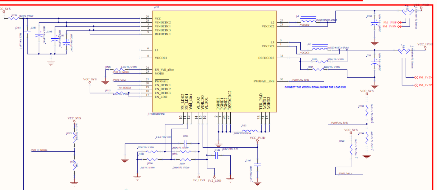
For test, I disable the EN_DCDC1 and EN_DCDC2. And connect the VDCDC3 PIN to a 3.3Ohm resist as a load. And the MODE pin of TSP650250 is tight to VCC_SYS. The VDCDC3 is designed to be 1.3V.

When the 3.3Ohm resist load is not connected, the L3 pin of TPS650250 is a stable PWM with a frequency=2.25MHz. Everything works OK.

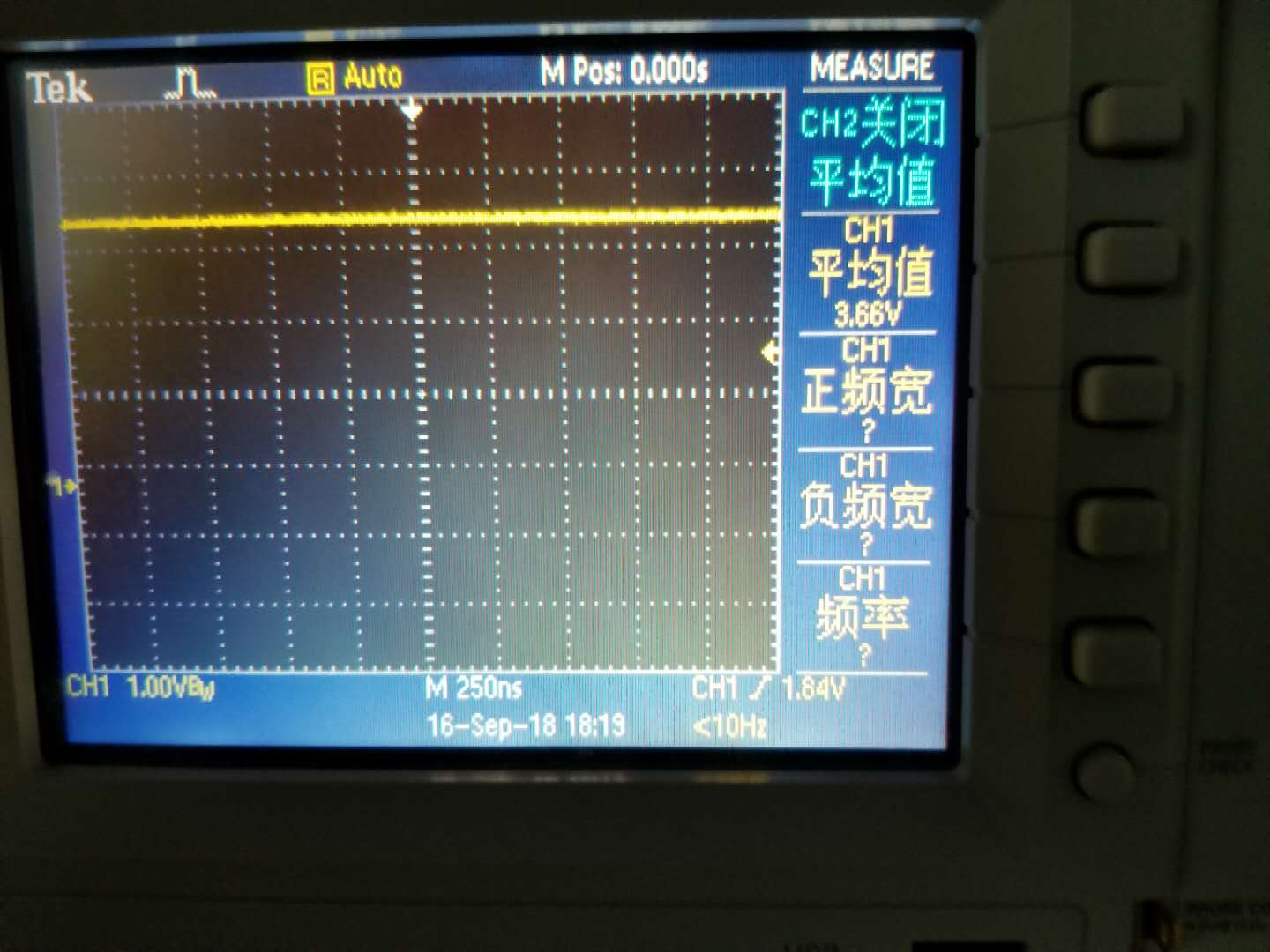
But when the 3.3Ohm resist load is connected, the L3 pin PWM output shakes a lot, while the VDCDC3 is still stable. But since the L3 PWM shakes, I can hear the noise.

Figure1 ---- L3 output:

Figure2 ---- VDCDC output = 1.3V:

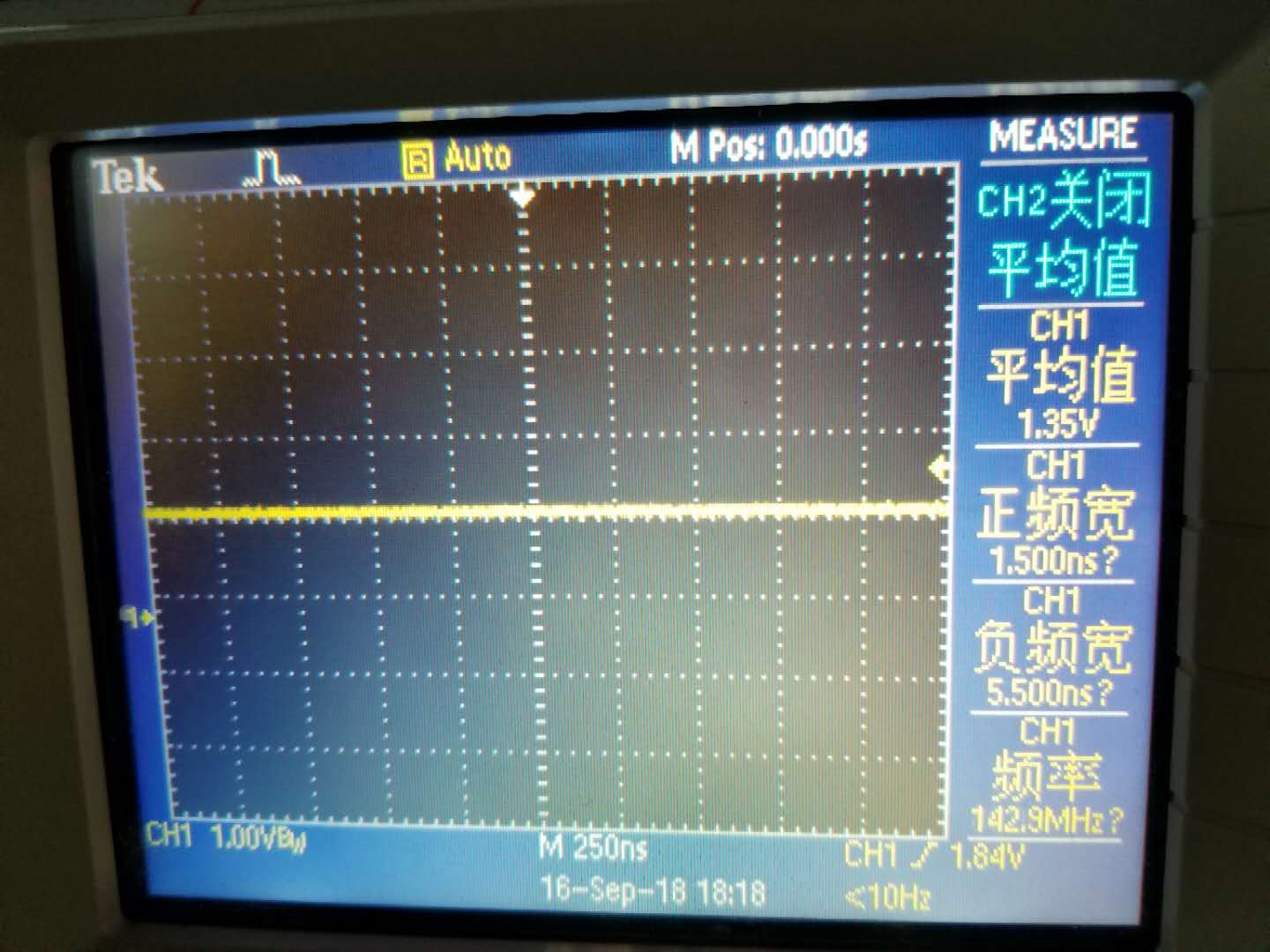
Figure3 ---- VCC_SYS input:

The inductor I use is VLS201612CX-2R2M, 2.2uH. And the output capacitance is 22uF.

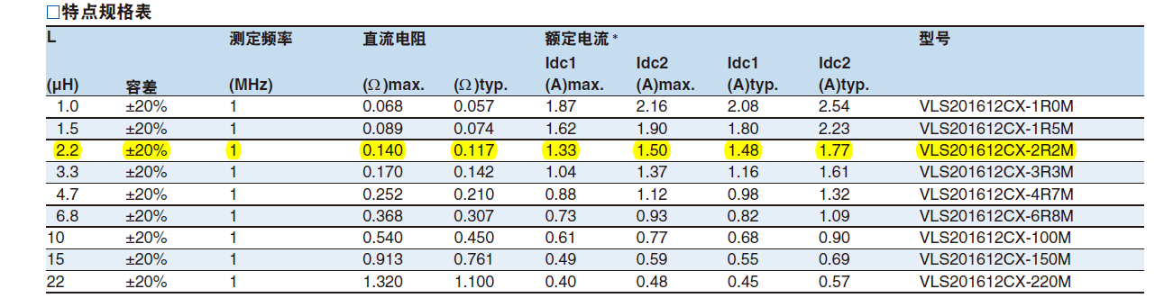
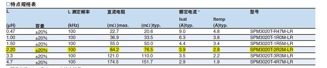
I also tried the 3.3uH inductor in the above table. But the PWM output still shakes.

And I also tried another 2.2uH inductor with smaller ESR, which is shown in the following table, but the PWM output still shakes.

The Question is: Why the L3 pin PWM output shakes?

Thank you.

  • Hi Frank,

    Generally the switch node jitter is an expected behavior for most of our DC-DC converters, but I have assigned this post to the part expert for more information.
  • Hi Kevin LaRosa,

    Thank you very much for reply.
    My application is wearable devices. The switch noise is too much, especially when the device fully runs. I can hear the noise even when the board is put into the shell.
    Is there any way to decrease the noise in the circuits?

    Thanks.

    Frank
  • Frank,

    When you say

    FrankXu said:
    I can hear the noise
    , do you literally mean you can hear noise with your ears?

    The frequency you are measuring is >>2.25MHz, probably on the order of 50-100MHz, which is the inductor "ringing" slightly when the switch turns on very quickly. This resonant frequency is unavoidable. It can be suppressed or moved, but it will always be present. As you mentioned, it gets filtered out at the load and there is mostly DC output voltage at the point of load.

    How do you know the source of the noise you are "hearing" is coming from this DC-DC converter in the TPS650250 device? Did you match the frequency of the noise to the frequency of the ringing when you probe this SW node?

    Thanks,

    Brian

  • Hi Brian Berner,

          Thank you very much for reply.

          Yes, I can hear the noise with my ears.

          When the load is not connected, the PWM is stable with a frequency of 2.25MHz, and the noise can not be heard.

          When the load is connected, the PWM shakes and the noise can be heard. So I think the nosie comes from the inductor.

          Is the PWM shaking normal or abnormal?

          I think the if the load takes >0.8A, or if the current exceed the saturation current of the inductor, the PWM will shakes.

          But in my case, the load < 0.4A and the Isat=1.7A. So I think the PWM should be stable.


         Thanks.

    Frank

  • Frank,

    If you can hear the noise with your ears, then it is not coming from the PMIC (switching frequency = 2.25MHz) or the Inductor ringing (this frequency is >10MHz).

    The audible frequency band is 20Hz-20kHz, and the lower end creates frequencies usually heard on a subwoofer.

    The noise you are hearing is probably in the 1k-20kHz range, depending on the pitch, and you will need to look for some evidence of this frequency on your PCB.

    I found this interesting article on audible noise when using PWM LED drivers. Is it possible the load connected to the TPS650250 DC-DC converter is creating this noise itself? 

    Although I cannot say for certain what component or IC is causing the audible noise on your PCB, I can say that it is not the TPS650250 or the inductor because the fundamental frequency of switching is too high to be heard by the human ear.

    Thanks,

     Brian

  • Hi Brian Berner,

         In my pcb, I disconnect all the load from the TPS650250. And connect only the 3.3Ohm resist to the 1.3V output. The PWM is not stabe as shown in the Figure, and I can hear the noise.

         I have bought a TPS650250EVM-447 board, I make the same test on the EVM. But the PWM is stable and there is no noise.

         So, I think maybe it is because of the inductor or the capcitance. I remove the inductor and the capcitance from the EVM and replace them with these on my board. But the PWM is still stable and there is no noise.\

         Now the only difference is the PCB layout.

         I will make some other try.

    Frank

  • Have you considered that it could be the soldering of the TPS650250 on your PCB that is causing the issue? This is one of the only options left to investigate, based on my understanding of your design.

    Another possibility would be the PCB layout on your board vs. the EVM. Maybe you have a "stub" that is acting as an antenna and it is generating this un-wanted noise.