This thread has been locked.

If you have a related question, please click the "Ask a related question" button in the top right corner. The newly created question will be automatically linked to this question.

LM5113: LM5113 charge pump problems

Part Number: LM5113

Hi,

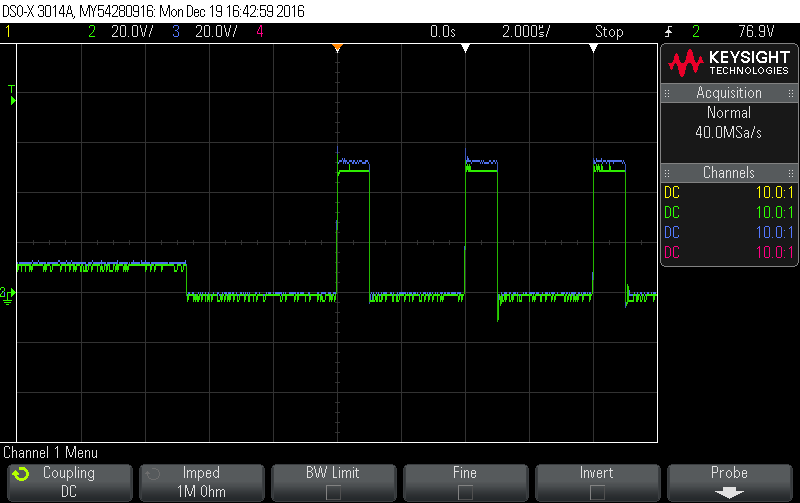
we are currently working on a DC/DC Converter witch should be able to work in either Buck or Boost mode. The DC/DC converter has two Low Side and two High Side GaN FET's (EPC2021) in parallel per half bridge. During the first startup of the DC/DC converter we encounter a problem with the charge pump of the LM5113. In the first scope below you can see the HS node in green and the HB node in blue. The settings for our converter was buck mode with a dutycycle of 25%.

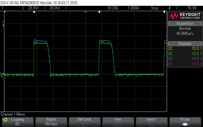
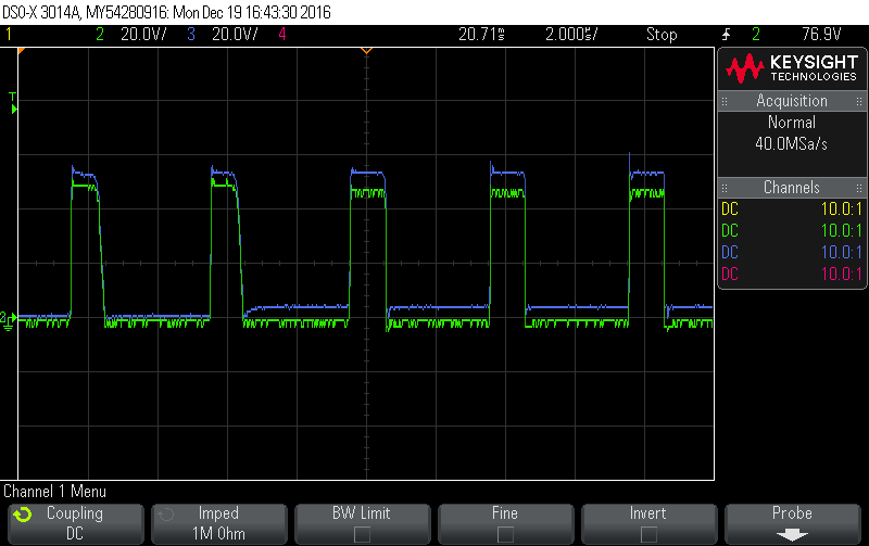
We expected to see that the HB node voltage rises when the Low Side ist turned on but instead we see no rise of the HB node voltage. The first 3-4 flanks of the High side look good but then we see an very slow falling edge (on the second scope). In scope 3 we can observe the behaviour of the voltage on the HB node rises after about 15-20ms. From there on the DC/DC converter works well.


Have you seen such a problem before? Any advice?

  • Hi Sascha,

    the reason why you are seeing the HB voltage behaving as captured in your screen shots is that the LM5113 does not have a change pump but an internal bootstrap diode.

    As shown on page 10 of the spec sheet:

    Therefore after power is applied the HB capacitor cannot charge until the low-side FET is turned on, and depending on: the size of the Vcc cap, the HB cap and the time the low-side switch is turned on, you will need a certain amount of time before the HB cap reaches its operating voltage.

    What you are seeing on the third screen-shot is the delay for the clamp to become fully active, and what you have on the first high-side pulses is a partially charged HB that could trigger UVLO on the high-side hence shorten the on time for the high-side FET for the initial pulses.

    Regards,

    Alberto

  • Hi Alberto,

    thank you for the fast response.
    But as you can see in the first screen shot the low-side FET ist turned on for about 4,5µs. We think that time should be enough to charge the HB cap. In the third screen you see a charging time of around 200ns what matches that theory. Our Vcc cap is 1µF and the HB cap is 100nF.

    Can you show me the internal circuit of the block UVLO & CLAMP for a better understanding what the driver is doing?

    Today we encountered a new behaviour. We have 8 phases in our DC/DC converter and at the first startup all phases had the behaviour that we describe ahead but on one phase the HB node voltage doesn't rise after 15ms. The DC/DC converter was on for about 10min but we still have very slow flanks on that phase.

    Do you have an explanation for this behaviour?

    Regards,

    Sascha

  • Hi Sascha,

    the HB capacitor indeed charges in ~200ns, as expected from the values you picked and what is captured on the screen-shot (at the third cycle).

    The 4-5us delay is due to the clamp, of which I cannot share more information on this forum, but I will gladly contact you privately to discuss further.

    Regarding the misbehavior you experienced on  8-phase converter, that could actually be caused by a soft-failure (I would need more information/ screenshots to formulate a better hypothesis) . My first level suggestion would be to replace the misbehaving driver and check again.

    Regards,

    Alberto

  • This issue was solved off-line.