This thread has been locked.

If you have a related question, please click the "Ask a related question" button in the top right corner. The newly created question will be automatically linked to this question.

LMG5200: Use in multi-phase 48v boost configuration

Part Number: LMG5200
Other Parts Discussed in Thread: TINA-TI, , TIDA-00909

I want to use this module to boost 30v to 48v at loads up to 100W.

This seems to provide several challenges.

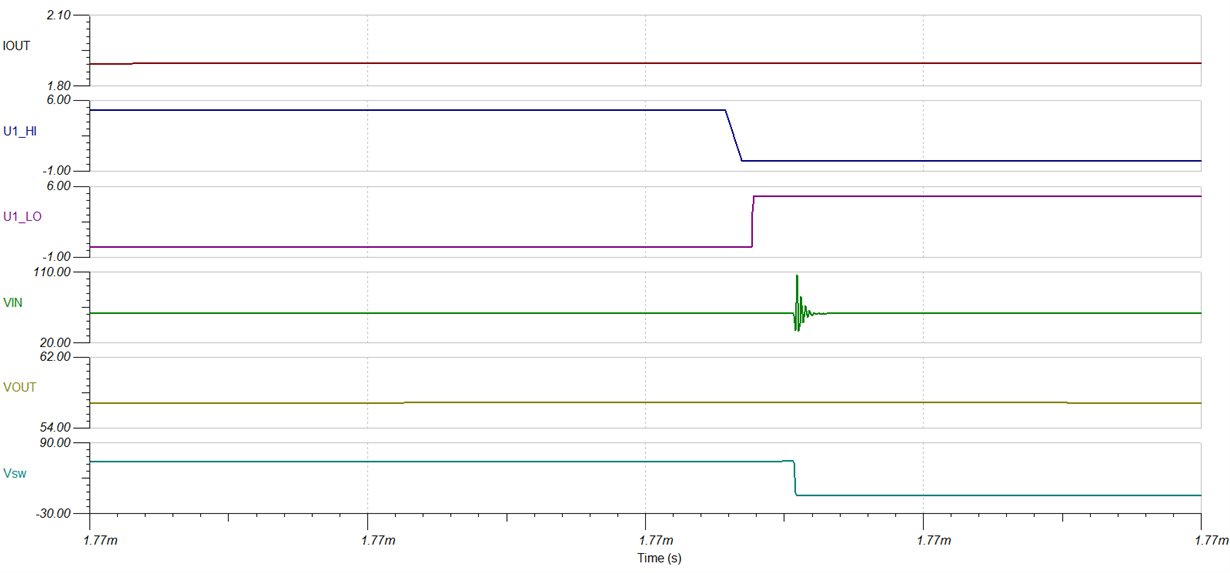
First of all there is the question of overshoot. In a slight adaptation of the reference TINA-TI schematic, voltage spikes of close to 100V were seen. What can be done to reduce/eliminate those? As I understand, 100v is the maximum allowed for less than 2% of the duty cycle. One thing I'm looking into is soft-switching, which is not trivial.

The other issue is that the grounds should not be connected externally. But with multiple phases, a loop is created through the internal ground connection of the other modules. How big of a problem is this, and how can it be dealt with?

  • Pepijn,

    Thank you for your interest in the LMG5200 GaN power stage. I ran a TINA-TI simulation on my end, whereby I modified the reference to create a 30V->48V boost converter. My sim does not show the magnitude of transients that you described. Perhaps you can share more details on the setup of your sim.

    In short, the best way to mitigate overshoot transients is to reduce power loop inductance. A tight power loop on your PCB will be critical. I recommend reading the Layout Considerations for LMG5200 GaN Power Stage application report. In the simulations, model the inductance on the input power supply side (~3nH or less, for example).

    With regard to grounding, with proper layout the control ground and power ground can be kept separate to avoid noise filtering to the control side. It shouldn't be an issue that the grounds are at the same potential, as long as the layout is such that the high-current path is not shared with the control-side ground. I recommend taking a look at the implementation in TIDA-00909. This is a brushless dc motor drive reference design using the three LMG5200s. You can see how the layout implements a single control ground and a single power ground. The source files and gerbers are available for download.

    I hope this helps. If this post answered your question, please press the "Verify Answer" button below.

    - Daniel

  • I attached a screenshot of the simulation, where you can see 100v overshoot on VIN, and the modified file: www.dropbox.com/.../snom478c.TSC

  • lmg5200_boost30-48V.TSCPepijn,

    Thank you for posting your simulation file. I have downloaded and run it on my end and see the results that you described. I have a couple of recommendations: The transients on VIN will be affected by the parasitic inductance. I notice your sim uses 1nH. In a circuit board, with careful design, the inductance can be in the 300nH range. I also noticed that the ramp settings for the soft start cause a very rough wake-up sinceit was starting with 100% duty cycle on HI. I switched the logic for HI and LI, since the main switch is the low-side on a boost (vs the HS on the buck). I also adjusted the ramp endpoint so that the nominal output is 48V. My sim file is attached to this post. In my sim, transients go up to ~70V, which is well within the device capabilities.

    I will follow up and take some boost data on the EVM to look at real-world performance. Please allow me a working day or two so I can make some time for this.

    - Daniel

  • Pepijn,

    I have not managed to set aside time to perform this verification since my last post. Apologies for the wait. I should have these results by the end of the week.

    Thanks for your patience,

    - Daniel