This thread has been locked.

If you have a related question, please click the "Ask a related question" button in the top right corner. The newly created question will be automatically linked to this question.

LMG5200: Datasheet indications to calculate switching losses

Part Number: LMG5200

Hello TI
I'm interested in using your LMG5200 and wanted to calculate losses for my application. However, I'm not able to find indications about Switch Transition time (p. 15, formula 5) or equivalent Information (gate resistance, switching charges Qgs, Qgd, ...) usually given in datasheet parameters.
Where can I find this Information?

Regards

Beat Ronner

  • Hi Beat,

    thanks for the interest in the LMG5200.

    To calculate losses during the switching transition, consider that the switched node slew rate is typically 25V/ns (with a max of 50v/ns). So at a given operating voltage you would be able to estimate the time base for the V-I overlap losses.

    Pvi = (Vin^2 *Isw) / (25*2)  (in nW) 

    Regarding the gate losses you can find the operating current at a given frequency from a 5V supply on figure 1, this includes driver and gate losses.

    By adding those into the other loss elements you will be able to get a good estimate of the LMG5200 power losses.

    I hope this addresses you question.

    Best regards,

    Alberto

  • Hi Alberto

    Thanks for your informations. Where did you get the 25V/ns from? I found the 50V/ns as "recommended operating conditions", but I could not find the 25V/ns in the datasheet.
    And, to my understanding, since this is the node slew rate, it indicates the time for the change of uDS. But a part of the switching losses is also generated during the change of iDS.
    How can I estimate this time?

    Regards
    Beat
  • Hi Beat,

    you are correct, the 25V/ns is not in the datasheet yet but will be added in at the next publication.

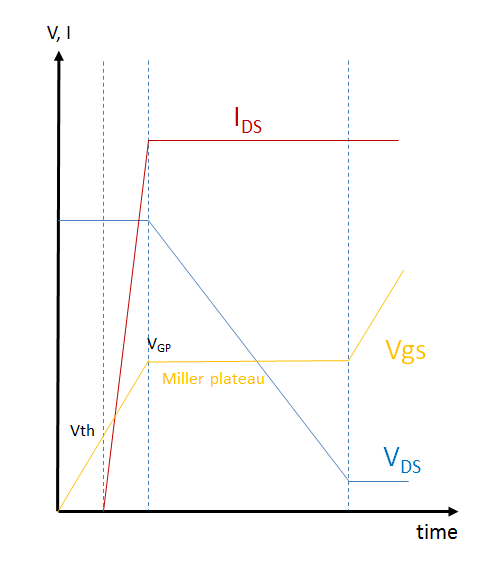
    Also regarding the V-I losses this method takes into consideration only the dVds portion,ignoring the dI portion.

    The calculation becomes an approximation but by looking at the typical waveforms (drawn below) it is possible to observe that the portion of time to transition from Vth to the Miller plateau voltage is significantly shorter (<20%) than the time it takes to get past the plateau.

    I hope this gives you a precise enough estimate  for what you need.

    Please let me know if you have any further question.

    Thank you!

    Best regards,

    Alberto

  • Hi Alberto

    Thanks a lot for your answer.
    Yes, would be good indications are in new Version of datasheet.

    I selected "This resolved my issue", but asked a new question about 3rd Quadrant voltage drop

    Regards
    Beat