This thread has been locked.

If you have a related question, please click the "Ask a related question" button in the top right corner. The newly created question will be automatically linked to this question.

UCC28701 IDRV peak current permitted

Other Parts Discussed in Thread: UCC28701

Our customer has questions about UCC28701.
I'm posting the questions for a customer:

++++++++++++++++++++++++++++++++++++++++++++++
They observed the current of the DRV terminal of UCC28701.

The peak sink current:IDRV(peak) was 158mA(max) on their board.

The datasheet mentions "Continuous gate current sink: 50mA(max)"
(ABSOLUTE MAXIMUM RATINGS).
But no mention of "Peak gate current sink" in the datasheet.

1)Is the peak:158mA(max) OK?

2)How much is the value permitted of "Peak gate current sink" for UCC28701 ?

++++++++++++++++++++++++++++++++++++++++++++++

Thanks in advance.

Best regards,
Takishin

  • Question 1: Is the peak 158 mA max OK?

    This depends on the gate drive wave shape. The data sheet parameter for maximum continuous current is for RMS. The term “RMS” stands for “Root-Mean-Squared”. Most books define this as the “amount of AC power that produces the same heating effect as an equivalent DC power”. Mathematically, the RMS value is the square root of the mean (average) value of the squared function of the instantaneous values. 

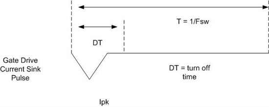
     More than likely the 158 mA peak is nowhere near the 50 mA RMS current maximum. The typical gate drive current sink is shown above. From my power supply text book “Fundamentals of Power Electronics” by RW Erickson, which every serious PS engineer should have, I find the formula to convert the peak current to RMS current to be the following: Irms=Ipk*SQRT(D/3). Where the SQRT() indicates square root and D = DT/T. For example if your driver is switching at 135 KHz and DT or the turn off time of the MOSFET is 100 ns, the RMS current would be 15 mA.

    Question 2: How much is the value permitted of “Peak gate current sink” for UCC28701?

    It depends on the waveform. In general, the larger DT is the lower the Ipeak can be. The reason there is no mention of the peak current is that the gate drive wave forms vary depending on application. Therefore a peak current would be impossible to specify. By definition, the RMS value gives the heating effect of the sink current and that is all that is important. You don’t want to fry the chip’s wire bond or send the PN junction of the totem pole into thermal runaway.

    So if you doubled the peak current and cut the turn off time in half in the example I mentioned above you would obtain an RMS current of 21.2 mA. And that would still be fine, it’s only about 25% higher RMS current even though the peak current has doubled.

  • Hi, Chuck

    Thank you very much for your answer.

    Best regards,

    takishin

  • You're welcome. Glad to help.

    V/r,

    Chuck Sampson