This thread has been locked.

If you have a related question, please click the "Ask a related question" button in the top right corner. The newly created question will be automatically linked to this question.

UCC25600 output shortcircuit protection ?

Other Parts Discussed in Thread: UCC25600

Hi Everybody,

Made a LLC converter from 400V to 48V, 400 watts using UCC25600. It's works great and functions at 90kHz, zvs archieved and control loop is stable. Also OC protection works ok as I limit the current to approx. 8A.
However, I notice the output current will not be limited in a case when I shortcut the output ??  The measured output current is even 8..10A  @ 0.5V. and frequency increases to 170kHz.

How to reduce the output current in such a condition ? Furthermore increasing the frequency ?

Thanks, Edwin

  • Hello Edwin,

    Congratulations on your successful design. I had the same issue with my LLC. I attended the SEM1900 a few year s back and decided to use a external short circuit protection that basically opens a load switch between the rectifier and the converter input. The problem with increasing the frequency to reduce the transfer function gain is described below. You can do it, but it's risky.

    I copied the following from "Designing an LLC Resonant Half-Bridge Power Converter, SEM1900, Topic 3, which I also attended. The author is Hong Huang.

    Load Short Circuit

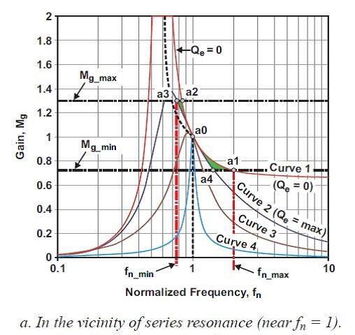
    "Since a load short circuit causes a potentially excessive amount of current in the converter circuit, it is necessary to examine the gain plot of a load short circuit to know what happens and how to deal with it. The corresponding gain plot is shown by Curve 4 in Fig. 7a. fc0 will become f0 when Lm is bypassed by a load short circuit, and this defines Curve 4 as the gain shape with a shorted output. Curve 4 provides insight into possible solutions for protecting the LLC converter. One possibility is to increase the switching frequency to reduce the gain. Based on Figs. 6 and 7, if the switching frequency is increased to more than two times the series resonant frequency (f0), the gain will be reduced to below 10%. If the frequency can be pulled up to ten times f0, the gain becomes practically zero. From Equation (25) it can be seen that a zero gain transfers a zero percentage of input voltage to the load short circuit. In this way, the converter can be protected from a load shortcircuit fault.

    However, it is worth noting that the effectiveness of such a protection method depends on how quickly the short-circuit signal can be sent to the controller to activate the frequency increase. In the recommended design area, the gain will inevitably be forced to the left side of the resonant peak for some time until it eventually reaches Curve 4. This could cause several severe issues, including the possibility of a polarity reversal of the feedback control. Considering this, an independent overcurrent shutdown may be a preferable solution. However, if a frequency increase is still preferred, two other possible solutions are recommended.

    Either (1) add a separate high-speed control loop to rapidly initiate the frequency shift, or (2) shift the recommended design area to where the minimum switching frequency (fn_min) is never less than the series resonant frequency (f0)—i.e., to where fn_min ≥ 1."

  • Hello Chuck,

    Thanks for your complete answer ! This is exactly what I needed. Indeed, the paper from Mr. Hong Huang is a great reference material. For the moment I leave the current protection at 9 amps, which can withstand the shortcircuit protection and also limit the frequency increase to avoid risky senarios. 

  • Glad I could help, Edwin.

  • Edwin, 

    Coutd you mark the question as answered? I got a bar bet with a colleague that I can hit 1000 before the end of the month.

    Thanks,

    Chuck