This thread has been locked.

If you have a related question, please click the "Ask a related question" button in the top right corner. The newly created question will be automatically linked to this question.

TPS28225D

Other Parts Discussed in Thread: BQ500410A

Hi,

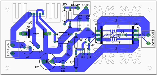
I have some issues building the circuit below. I have problems gettign teh TPS28225D to work properly. I am trying to build a wireless power transmitter, however, when i connect the transmitter coil to the OUT1 and OUT2 connectors, the UGATE voltage of the IC fails. Without the coil, the IC provides good voltage levels. I just cannnot figure it out. I assumed the PCB layout may not be good, otherwise i am using the exact same schematic as the BQ500410A wireless power transmitter uses. The bootstrap and drive capacitor values are the same as well.

Thank you in advance for your help,

Best wishes,

Balázs Salamon

  • Hi Balazs,

    You need to check the coil. The coil has to have enough inductance to support the voltage output of the IC. 

    You don't say whether you have an air coil or are using ferrite.

    To calculate the number of turns needed in your coil using a ferrite core, you have to know to things: the maximum B, or flux density your coil can support without saturating, and the ET, or volt-sec you will put across the coil. The formula is the following:

    N =ET/(B*Acore)*10 ^-8. 

    The 10^-8 reconciles the units for Gauss and volt-us.

    For an air core do the following. Calculate the maximum driver current from out1 and out2. The impedance of the air coil must be high enough so that when you multiply Imax of out1 times the coil impedance you get the driver voltage. The formula for the air coil inductance is the following:

    L = (r^2 - n^2)/(8*r - 11*W)

    This formula is called the Wheeler formula for a pancake coil. It is pretty accurate. You need to use this equation to make sure you have enough turns, n. W is the space between the coil turns. r is the radius of the coil from the center to the outer layer.

    I do think you may have a problem with your circuit. C5 is going from the PWM IC out to C5 to pin 2 on U1. Where is your coupling cap for U1? You need a good size coupling cap, 1 uF or larger at pin 6 to ground. The cap should be placed as close as possible to U1.

  • Hi Chuck,

    Firstly let me thank you for your thorough answer. I am using an air coil, since the circuit is supposed to be a wireless charger. I did measure the inductance of the self-made coil with a maxwell DMM. The best accuracy of the DMM is mH, but it said the coil had a 0.009-0.011 mH inductance. The market devices use coils with 6-24 uH inductances.
    I am going to try and use different coils or modify the one i am using right now.

    The track for C5 is indeed connected improperly, i have already soldered it directly to the IC's pins, but it didn't solve the issue. The coupling capacitor is C4, which is currently 220nF. Texas Instruments was using a 100nF there, but I figured it might not be enough, i will definitely try using a higher capacitance capacitor.

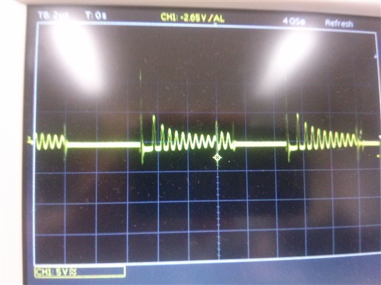
    This the UGATE voltage with the coil, it should be a square wave, it never opens the high side FET like this, so the coil never actually gets charged i think. The waveform actually looks like something is resonating, i thought that the C5 trace to pin8 may have a large enough inductance, that it creates a self resonant circuit, but as i mentioned it earlier, soldering it directly to the pin didn't solve the problem.

    I know the PCB layout isn't great, but i had to do this on one layer. I simulated the entire design in PSpice, using OrCAD,it worked exactly as it should. I used an inductance value of 5 uH for the coil.

    I dont know what could cause the problem, C4 is not close to the IC, so that may be it.

    Thank you very much again for your help, i really appreciate the time you actually took to answer me.