This thread has been locked.

If you have a related question, please click the "Ask a related question" button in the top right corner. The newly created question will be automatically linked to this question.

UCC28711 Not at all powering up, Tried all methods

Other Parts Discussed in Thread: UCC28711

Hi,

      We have a problem with UCC28711, it is not power up at all. We changed the IC, We changed the MOSFET and did everything. Still it is not Producing any pulses.

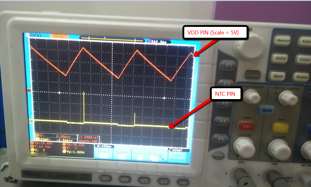
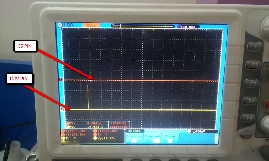
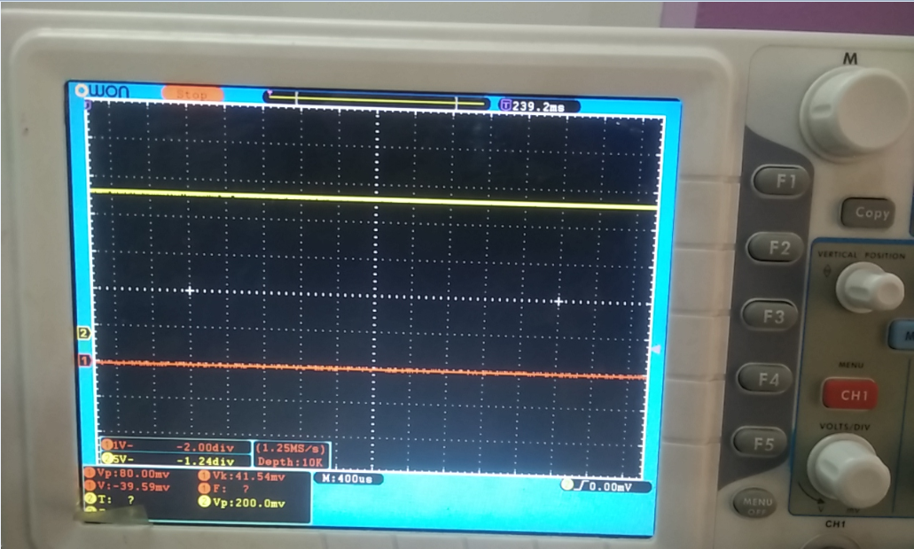
We saw a strange behavior in NTC pin. Please find the attached waveforms.

Red: NTC Pin ( 100K connected between NTC and GND, note that NTC Pin is going to 20mv and going to zero)

Yellow: VDD Pin

  • Hello Amruth,

    Did you use any external startup circuit for UCC28711, or have you directly connected DC line to HV pin?

    It is not recommended to use any external circuit to startup UCC28711.

    Thanks,

    Yash.

  • No external startup, right now we tried DC Line voltage upto 200V. It is not even giving first three pulses.

    MOSFET: IRFBG30, Ciss = 960pF

    Transformer: 2.3 mH

    We changed two IC's. But no luck, Gate pulses are nil.


    Amruth

  • Hi Amruth,
    Could you let NTC open first? it should work with NTC open. from your waveforms, seems there is wrong with NTC resistor or NTC pin of IC.

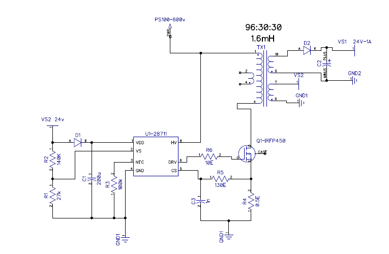
    btw, could you attach the schematic to let us review?

    Br
  • Hi Ben,

                   We had remove the NTC Resistor before, with no luck, same pattern.

    Please find the attached schematic.

  • Hi Amruth,
    Could you capture the first (three) pulses of DRV if it has three? in the same plot, it should include CS and AUX waveforms.
    From your schematic, i think two value are not proper. first is the C3, its value is too high. please remove it.
    second, the C1 value. i think you may use 4.7u or 10u ceramic capacitor instead.
  • Dear Ben,

                        We made the changes  as below

    1) Removed NTC Resistor

    2) Removed the C3 Cap

    3) Remove C1 cap and added 10uF, Electrolyte cap

    Attached are the waveforms

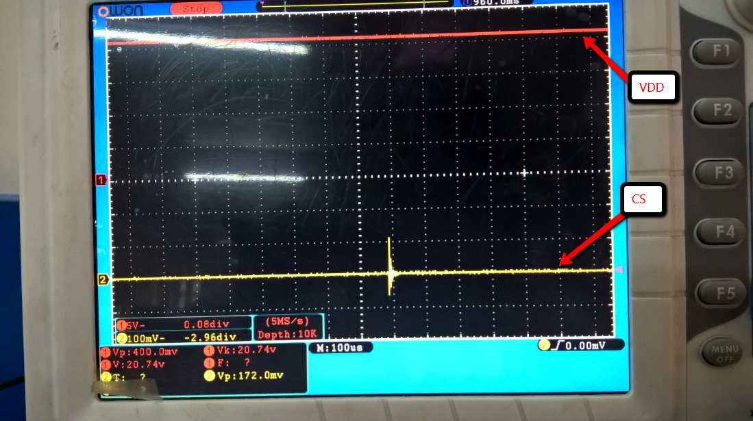
    1) VDD - DRV

    2) VDD - NTC

    3) CS-DRV

  • Hi Amruth,

    could you zoom in the waveforms after the three steps?

    The aim is to look at the waveform clearly. VDD is not needed.

    For the time zone, i think you should use ~us/div instead of 400ms/div.

    For the CS waveform , please use 100mv/div.

    For the auxwinding(VS2-24V), it is also needed.

    How many pulse was made every time?

  • Hi Ken,

                   DRV pin occasionally produces single pulse.  We found some co-relation in that When NTC Voltage > 1.5V, then we saw single DRV pulse at the valley peak of VDD.

    Many events only used to occur at the valley peak (21V), so we plotted that as reference.

    Ok, we will send the waveforms as per your request in an hour.

    Amruth

  • Hi Ken,

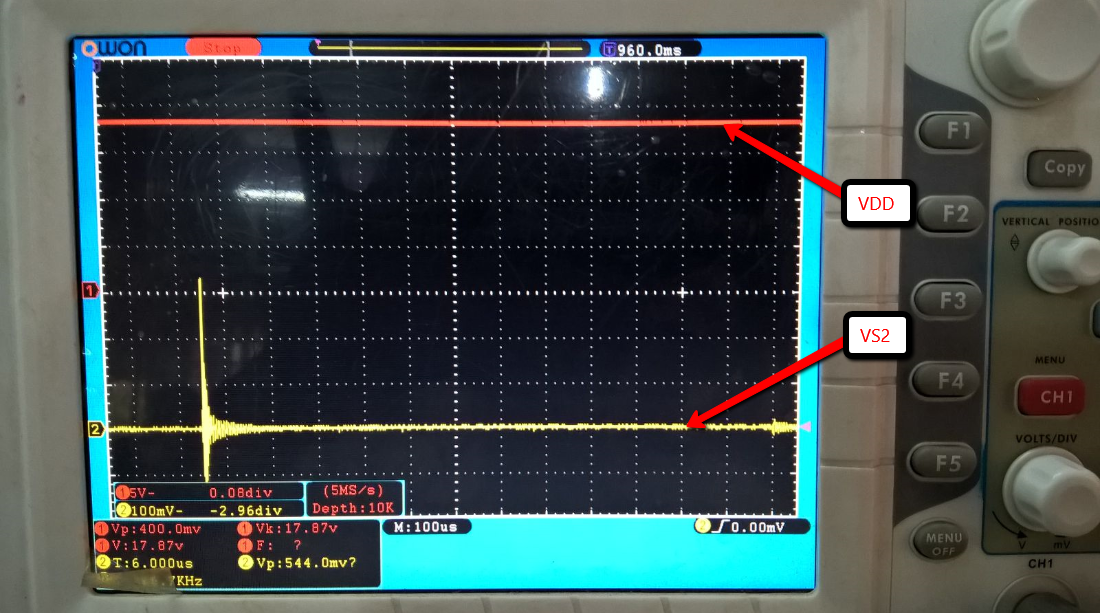
                    Please find the attached waveforms as per your request. The thing is we cannot capture wavefroms without vdd as reference, as pulse comes only when VDD = 21 V or higher


    1) VDD-CS ( Note: CS is at 100 mv)

    2) VDD-VS2 ( Note: VS2 is at 100mv)

  • Hi Amruth,

    The sample rate is too low(5MS/S) , and the timeline is too big(100us). 1us/div shuld be better scale.  I cannot see it clearly.

    You may check it first. please check at your MOSFET working.

    From your waveforms, seems the MOSFET doesn't turn on when there is pulse at DRV pin.


    Br

  • Ken,

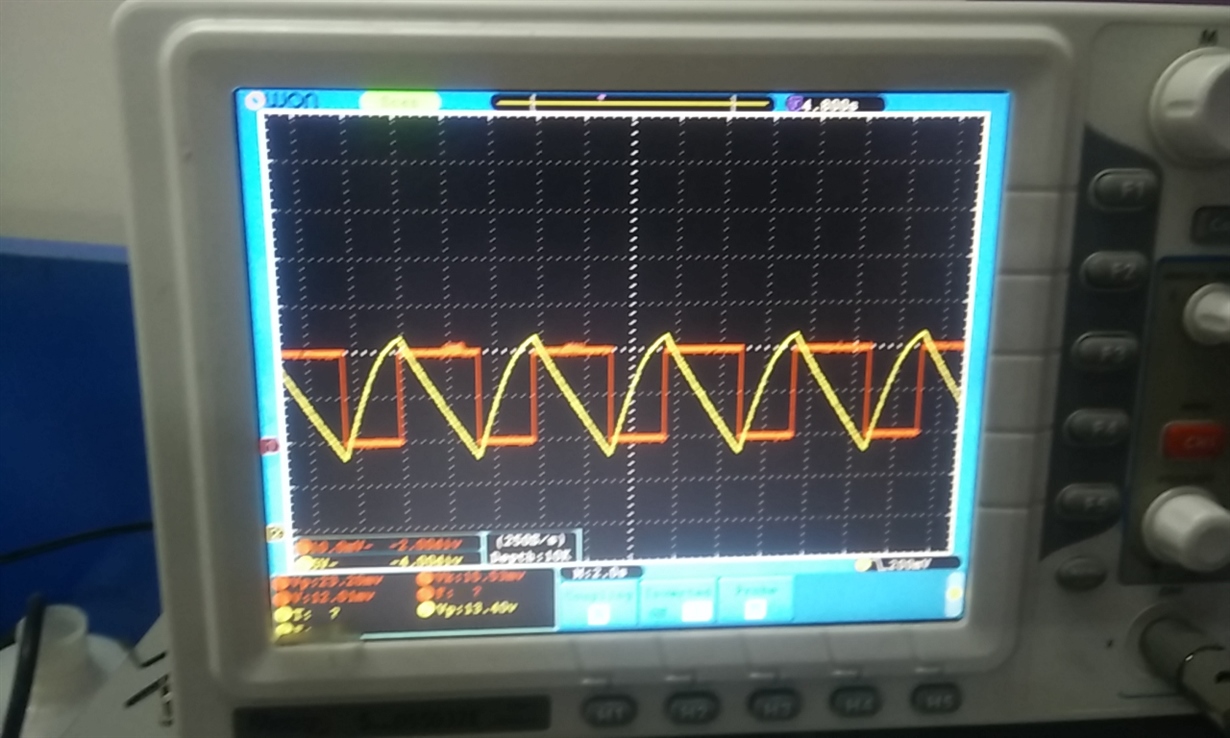
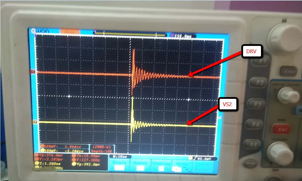
               It is very hard to capture at 1us/div. The smallest we got was 20us/div.  We found strange drive signal, it looks more like a ringing signal than Gate Drive signal.  This is little strange for us. Also please note we are giving input voltage upto 100V, for now. Hope that is not the limitation.

    Additionally, we are using  IRFB450 and IRFBG30. The below signals are with IRFB450.  But we think same might be true with IRFBG30 also.  Is there any specific limitation with MOSFET's ?

    1) DRV-VS2

    Let us know if you need signals with IRFBG30.

  • Hi Amruth,
    The Input capacitance of IRFB450 is too high (3180pf). The driving capability of UCC28711 is not enough for this one.
    Please try IRFBG30 which has a smaller input capacitance.


    Br
  • Hi Ken,

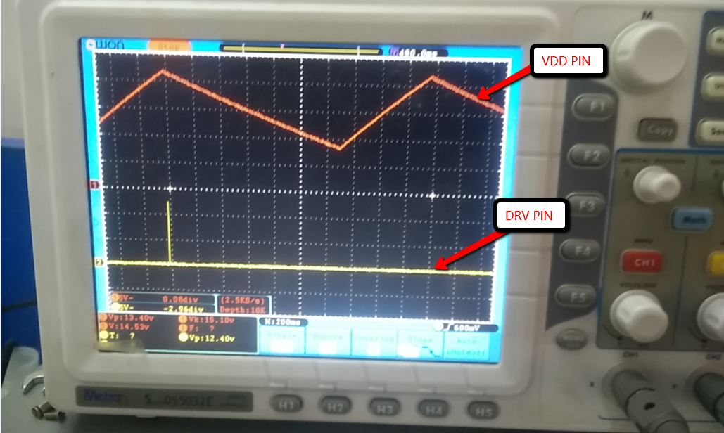
                We changed the MOSFET to IRGBG20, but now not a single pulse at all. VDD is same as earlier charging and discharging, but not pulse during Vdd = 21V.

    Please find the attached waveform.

    1) Yellow = VDD

    2) Red = DRV

    To limit the current we changed the DRV gate resistor from 10 ohm to 1K , but not effect.

    Are we missing anything ?

  • Even you don't assemble MOSFET on the board, there should be pulse on DRV when VDD reach ~22V.
    Please check your connection.
    And don' t use 1k as the Gate resistor. zero ohm is ok.
  • I think something went wrong, no pulses at the DRV when MOSFET is removed, even after VDD ~21V.

    We will assemble new board with new IC and get back to you.

    So, if MOSFET is not there, how many pulses it should produce ?

    Amruth
  • Hi Amruth & all,

    I am also using UCC28711D for my high voltage ( Vdc > 800V) SMPS ( 153 watt).

    And I also have faced these problem. And more surprisingly I have faced these problem in one of my 2 PCB where has  in the other PCB it is working fine. Though both the PCBc are identical regarding the component & layout.

    The power up of this IC seems to be a problematic factor. The other performance like efficiency & regulation are superb for this IC.

    However from my experience I have observed the following factor:-

    1. while VDD reaches 21V the DRV pin release one pulse ( though in datasheet it is said that three pulses will be given). Some time I have seen three pulse but most of the time it release single pulse.

    2. just check whether any protection is getting active or not ( in my case high voltage > 1.5V was coming at CS pin).

    3. Arrange totem poll configuration for driving ur MOSFET. IC can give only 25 mA gate current.

    4. Try by changing the xmer. Put proper air gap as per calculation. I have observed my SMPS now working with slight modification in air gap.

    5. make pin 3 open ( NC).

    6. In my full load at low voltage I have seen the switching frequency at 33 KHZ. Though my xmer is designed for 100 KHZ. I have not understood this.

    7. after releasing one pulse if IC does not get any feedback then also it will not powered up.

    I am still struggling to make my SMPS fit.

    Good luck..

    Regards

    Raja Saha

  • Dera Amruth,

    Is your problem solved regarding UCC28711D based SMPS.

    Please let us know any further development on this, as it may help us also.

    Regards

    Raja Saha