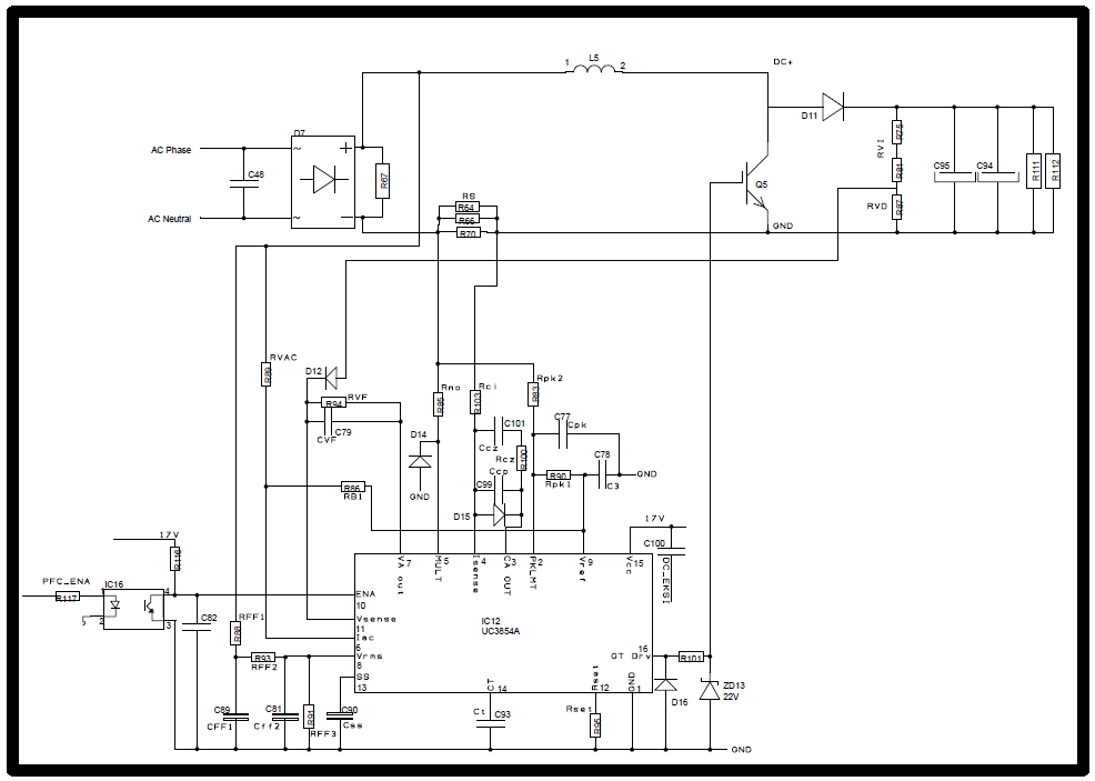
Hello everyone, I am here to ask some questions about a boost PFC circuit with UC3854 as a controller. I attached my schematic design.
This is for 2000W power output. My AC line is 170- 270V and 45-55Hz. My Inductor is 1mH and output cap is 2x470uF.
Shunt resistor (Rs) is 50 mR, Peak curent limit is 20A and switching frequency is 52kHz.
Below is the other important values that I used.
| Name | Ref. | Value |
| Rvi | R75 | 470K |
| R81 | 56K | |
| Rvd | R87 | 10K |
| Rs | R64 | 100mR |
| R66 | 100mR | |
| R70 | - | |
| Rvac | R89 | 620K |
| Rb1 | R86 | 150K |
| Rvf | R94 | 27K |
| Rff1 | R88 | 1M+27K |
| Rff2 | R93 | 180K//56K |
| Rff3 | R91 | 10K |
| Rset | R95 | 4.7K |
| Rmo | R85 | 1.2K |
| Rci | R103 | 1.2K |
| Rcz | R100 | 33k//33K |
| Rpk2 | R83 | 2.7K//2.7K |
| Rpk1 | R90 | 10K |
| Cff1 | C89 | 220n//47n |
| Cff2 | C81 | 470n//470n//220n |
| Css | C90 | 470n |
| Ct | C93 | 4.7n//470p |
| Cpk | C77 | 150p |
| Ccp | C99 | 100p//100p |
| Ccz | C101 | 1n//150p |
| Cvf | C79 | 470n//47n//10n |
I am watching the mosfet's gate with a scope. When I enable the IC, I see a few pulses and then nothing.
When woking, I don't see a "6V DC and a little sine" at pin 6. I see 0,5-1V DC. I measured 7,5V (IC's reference) at pin 9.
I see a 1,8-2V DC at pin 8 and I think this is normal for 220V AC line.
I saw triangle wave at 52kHz at pin 14 so the oscillator is working.
I saw nothing at all at pin 5, but I think I should have seen something since this is the control system output.
When I remove the inductor (output voltage feedback is not coming) the pulses are coming but I think this proves nothing.
Is there something wrong with the values I used?
Can you point me a direction?


