This thread has been locked.

If you have a related question, please click the "Ask a related question" button in the top right corner. The newly created question will be automatically linked to this question.

UCC28070 input current distorted / oscillation

Other Parts Discussed in Thread: UCC28070

Hello,

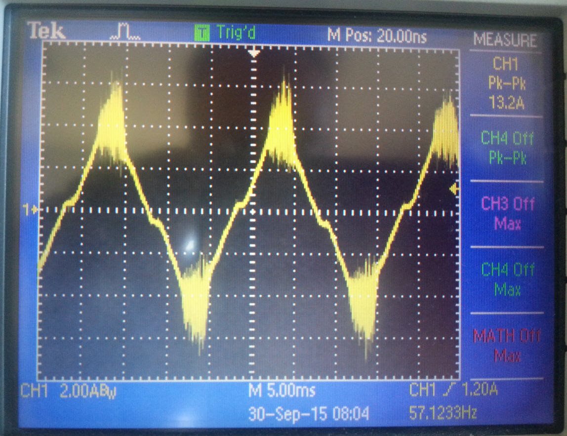
I have build a UCC28070 1800W PFC configured by using the regular TI excel sheets. First prototype is functional and loaded by 1kW / PFC is around 0.97, however when I measure the input current I notice in top of the current peaks a lot of ringing/oscillation, see picture below.
Does anyone observed this behavior and have an idea what could be the reason for this noisy input current ? 

Regards, Edwin


  • Hi,
    Can you provide more details on the test conditions?
    Input voltage, output voltage, load current
    The schematic also
    Thanks,
    John Griffin
  • Hello John,

    Thanks for your reply. The input voltage is AC mains 220V, which output voltage is 390V. The load current I limit t approx. 1 till 2 amps. The input current shows the distorted peaks already at lower power fe. 300Watts. The schematic is exactly the same configuration as TI UCC28070 reference. First I will measure the gate voltage for both PFC fets and disable EMI dithering (its enabled right now).
    Another point I suspect is the EMI effect of cree type boost diodes, which I need to check in coming days. Keep you informed.
  • Hi Edwin,
    Also please look at the inductor current on a shorter time base.
    Monitor inductor current and gate drive on same scope plot.
    It is possible that the inductor is saturating.
    Regards,
    john
  • Hi John,

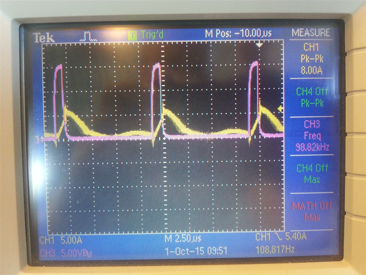
    Thanks for your support. I've measured both inductor currents and gate voltages and notice the currents show DCM mode at 300W. I would expect to see a CCM current ? I did not yet verified the CSA and CSB signals coming from the current transformers. Below picture shows the input current (yellow) and gate voltage (pink). Switching frequency is 100kHz correctly as configured. I will verify the CSA and CSB signals, but meanwhile I wonder which mechanism sets the start of CCM switching at UCC28070.. (or could disturb the CCM and switch to DCM). 

    Regards, Edwin

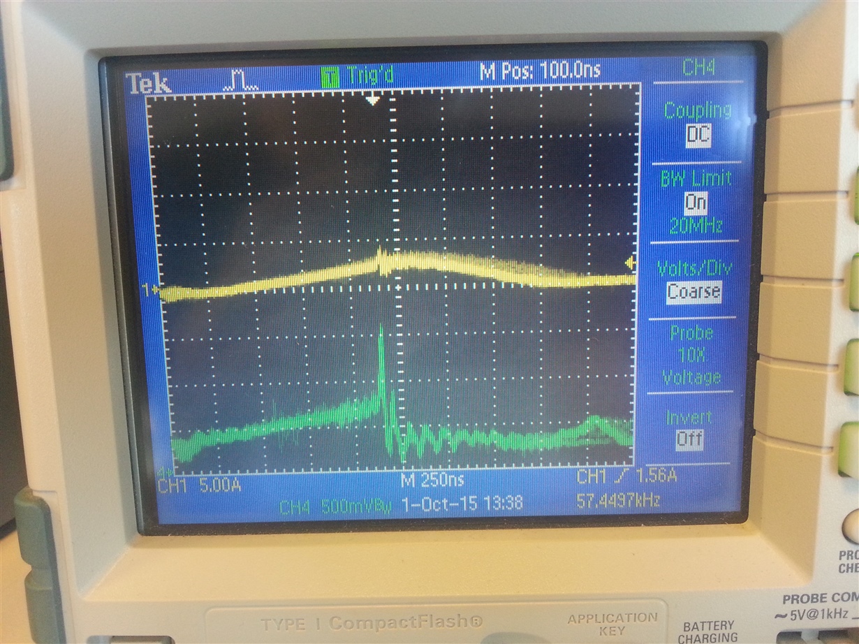
  • The CSA / CSB signal consists a peaking, probably introducing a false current trigger.. see green trace measured after current transformer at CSA.
    This is probably the reason why it remains in DCM mode. Does anybody know what could cause this peaking / ringing , since this causes probably
    the ringing also at my input current (yellow trace).

  • Hi ,

    Unfortunately didn't managed yet to reduce the distorted input current.

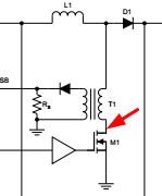
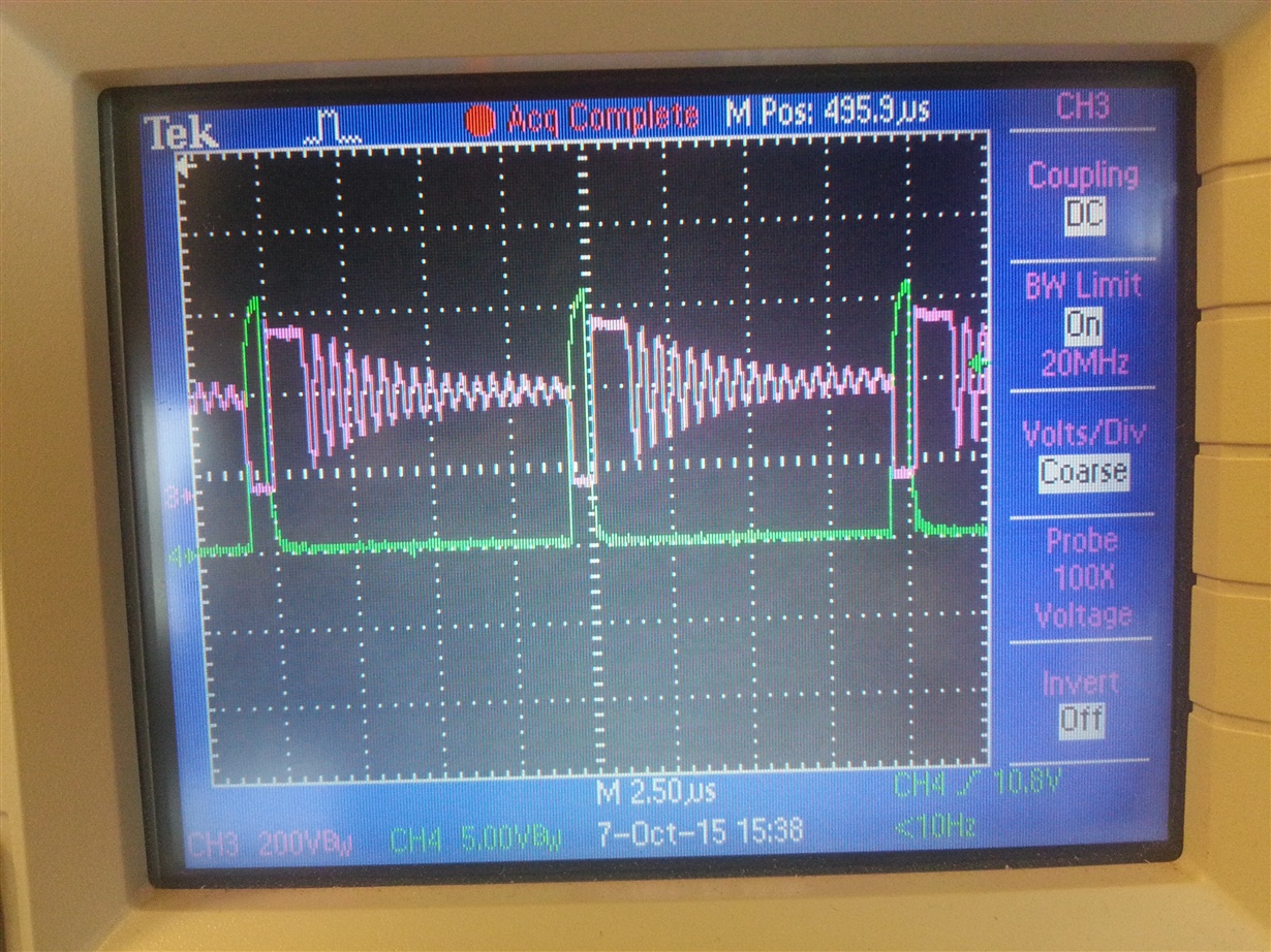
    I've measured the gate (green trace) & drain voltage (pink) of one PFC fet controlled by UCC28070.  When the FET is switched on and off I see a (ringing) voltage in case the FET is switched off.. It is a 500nS period (2MHz) which i also notice at the mains input current.. I would not expect this.. Any idea how to reduce this ringing ? Diode is a cree type and fet is Infineon Coolmos type.

  • Thank you guys for the great support. Problem has been solved.
  • Hi, Edwin

    Could you let me know how do you fix this oscillation issue?

    Regards,

    Yunsheng

  • Hi Edwin
    I have the same problem as yours. Could you say more about how to fix your problem.

    Regards,

    Ali Osman