This thread has been locked.

If you have a related question, please click the "Ask a related question" button in the top right corner. The newly created question will be automatically linked to this question.

UCC28070 PFC input current distortion around zero crossings

Other Parts Discussed in Thread: UCC28070

Hello,

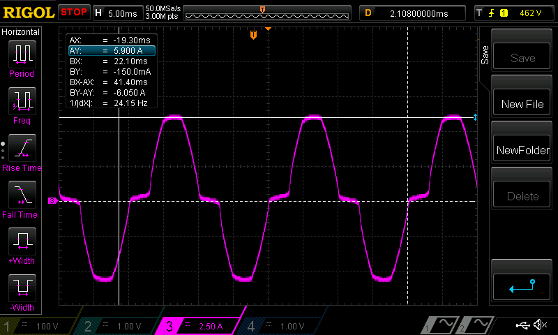
I am building 3500W PFC using UCC28070. Currently I am testing it with 1000W load using just phase A. I get significant input current distortion around zero crossings. See the picture attached. 

I used values provided by manufacturer's excel sheet. What causes such behavior, and is this normal?  Cheers.

 .

  • It may be that the capacitance on the DC side of the bridge rectifier is more than is required.
    If that is the case then the rectified voltage never drops to the low value associated with the zero crossings.
    The DC rectified voltage is higher than the line voltage for a significant time around the zero crossings and the reverse biased diodes make it impossible for the controller to pull current from the line.
    I think you should try reducing the capacitance.
    Incidentally, why have you disabled phase B and how exactly did you do this ?

    John Griffin
  • The capacitance on DC side of bridge was only 100nF. I tried reducing it to 10nF but nothing changed. Application note for 1200W PFC from TI suggests using even higher value (470nF).
    As for disabling phase B, I just didn't solder in power transistor and diode. I figured that it would be easier to make one phase work first.
    Do you have any other suggestion concerning current distortion?
    Thanks
  • What did you actually measure the THD and current harmonics to be ?

    What are your design requirements for harmonic distortion, power factor, input voltage and load range?

    Do you have a schematic and bill of materials ?

  • Hi,

    Could you please supply some more information to go with your picture?

    Vrms line voltage.

    A switching frequency picture of the pfc inductor current. Particularly in the area around the zero crossing where distortion is high.

    In this region does the pfc inductor current become discontinuous.

    This additional information may help us to answer your question.

    Thanks

    Joe Leisten

  • The problem is solved. It turns out that I had positive offset voltage in current sensing circuit. That way, the PFC controller would cut pulses early before zero crossing (of rectified mains) to try to bring the current down.

    Thanks for quick answers.

    Regards,

    Velibor

  • That is good news that the problem is solved.
    The data sheet recommends adding an offset to improve noise immunity around the zero crossings at very light loads.
    (page36 )
    Did you have too much offset added?

  • About 0.55 volts. This was the current measurement circuit used initially. Increasing R11 reduced offset.

    There is one other problem that I ran into. After confirming that each of the phases were working when used independently, I tested the circuit with both phases enabled. The converter would manage to reach desired output voltage (400V) under no-load but when loaded, voltage would drop to the level of rectified mains (around 300V). The windings on boost inductor for each phase are wound in opposite directions of each other. 

    What could be the problem here? If you need some more info, I will provide it.

    Thanks in advance,

    Cheers

  • I don't quite follow how the boost inductors are configured. Are both inductors wound on the same core /
    It seems that PHA and PHB are interfering with each other when they are both run at the same time.
    My email is johngriffin@ti.com if you wish to contact me

    Regards,
    John
  • Here is my schematic. Both inductors are wound on the same toroidal core. The polarity of windings is marked with dots in schematic. I will try using two separate inductors (on separate cores) to rule out the inductor as potential source of problems.

  • I tried using two separate inductors (on separate cores) and it seems to work well that way. If they are winded on the same core, then it does not work. Do you have any suggestions at to what could be wrong?
  • You have wound both inductors on the same cores with each winding out of phase with the other.
    I do not think this will work because the normal boost gain equation of
    Vout = Vin/(1-D) is not longer valid.
    For instance during the condition when one FET turns off and second FET still on, voltage across second inductor is
    Vin and Vin-Vout across the second winding.
    Because both windings have the same number of turns you need to have the same voltage across each winding.

    Regards,
    John
  • I looked into theory a bit, and you are right. Equivalent inductance in each phase varies depending on the voltage applied to the other winding. Is this IC (UCC28070) designed for use with coupled inductors, or is it intended to be used only with separate cores/inductors for each of the phases?
  • Right

    This ic is not designed for coupled inductors