This thread has been locked.

If you have a related question, please click the "Ask a related question" button in the top right corner. The newly created question will be automatically linked to this question.

UCC27611OLEVM-203 Not Operating

Other Parts Discussed in Thread: UCC27611

Hi Everyone,

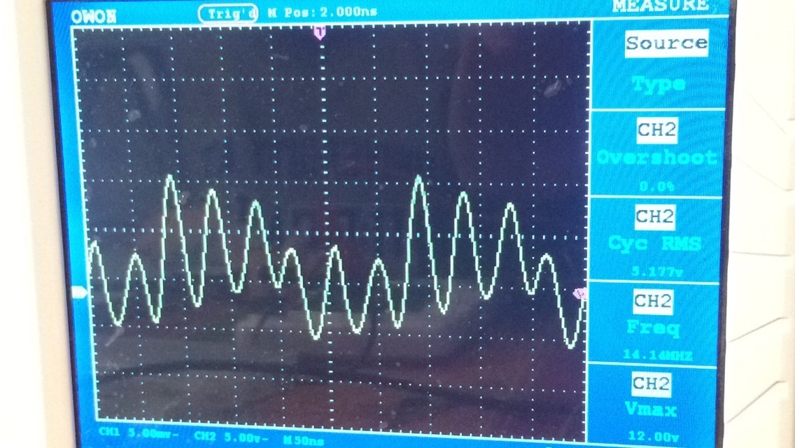
We purchased the UCC27611 evaluation module and have been experiencing issues with it. We conducted the test circuit setup to isolate the module from our transistor. Under no load conditions, the output consistently looks very noisy and we're honestly not sure why. We applied 10V to the Vdd pin and a 4MHz square wave to the Drive In pin. We are measuring the OUTL pin with J1 connected. Attached below is a picture of our output. Everything else seems to be working fine. It switches from an inverting to non-inverting setting appropriately and Vref is ~5V as well. We've tried multiple probes, oscillators as the pulse instead of our wave generator, and honestly don't know what else to try. This is the second module we purchased and the output looks exactly the same. Has anyone else experienced this? If anyone has any suggestions, we'd really appreciate it!

Thank you for your time.

Best,

Josh

  • Hi Josh,

    I will take a look into this and will let you know.

    Thanks and regards,
    Ritesh
  • Hi Josh,

    Did you ever connected this EVM to FETs or any other circuit?
    If you did connect the EVM to other circuit, did you check the performance of the EVM by itself prior to connecting it to other circuit?
    Would you please check the waveform from IC side of R1 pad (OUTH) to the TP10. Connect scope ground to TP10.
    It would also be helpful if you can capture waveform showing VDD, VIN, and above mentioned waveform.

    Thanks and regards,
    Ritesh
  • Hi Ritesh,

    The picture shown previously is over the OUTL pin during no load conditions with J1 connected. We previously tried connecting the EVM to an LDMOS FET we have and the output did not change from the picture shown previously. We cannot get the EVM working appropriately prior to connecting it to another circuit. We have conducted the Test Circuit Setup shown in the data sheet multiple times with different probes, oscillators instead of our wave generator for the Drive In pin, etc. and continue to have a distorted output signal. We have tested this on two separate modules and the results have been the same.

    The waveform over the OUTH pin and the R1 resistor is identical to the picture shown above.

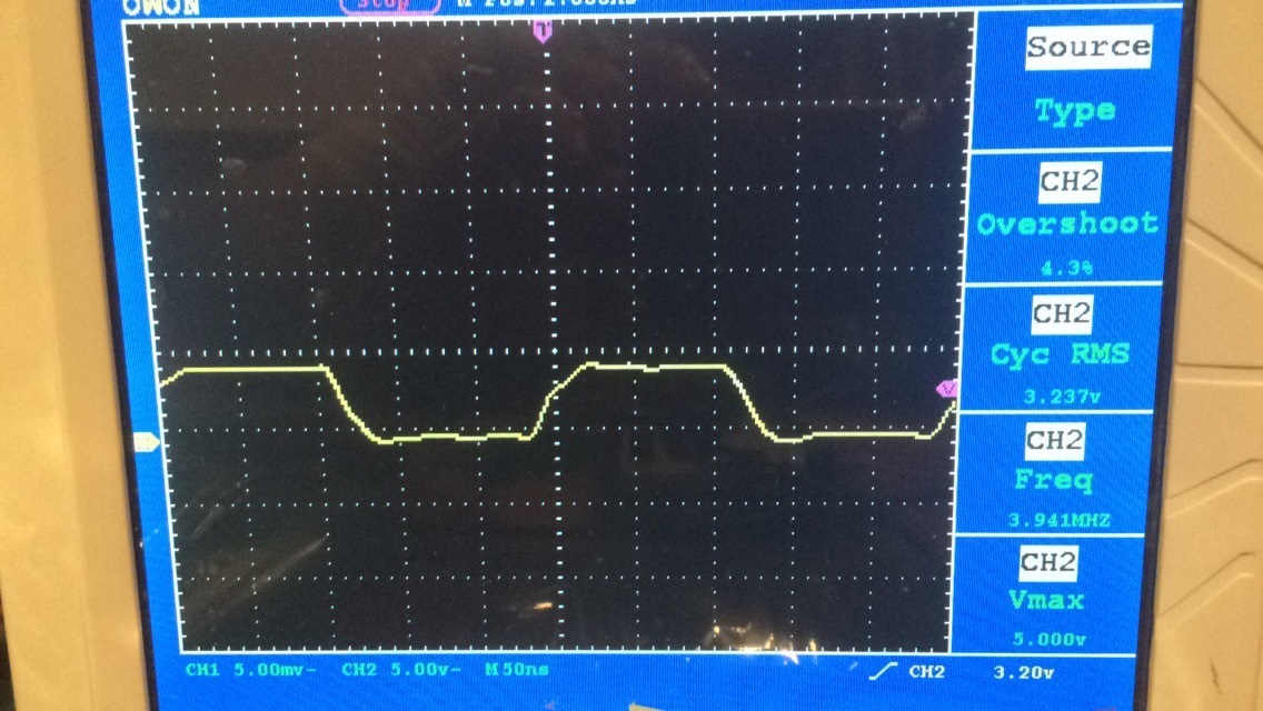
    The signal we are applying to the Drive In Pin under the Test Setup Conditions looks like the picture below. Furthermore, the non-inverting pin also looks like this when placed in a non-inverting setting.

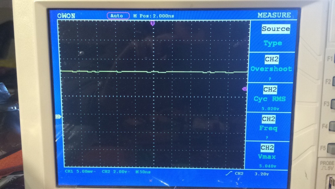
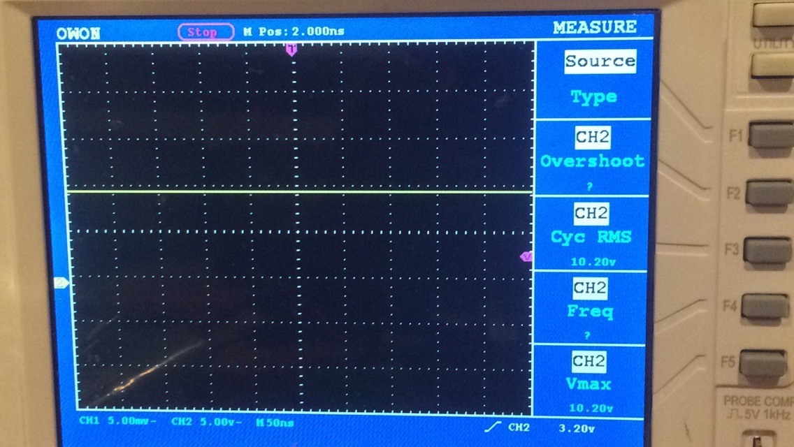
    The Vref looks like this:

    The Vdd looks like this:

    Lastly, the ground pins also appear to be grounded as well. This information appears to hold true at not only the test points on the board, but also the pins on the IC.

    It's honestly a pretty straight forward test setup, so we're not sure what's wrong.

    Thank you for your time.

    Best,

    Josh
  • Thanks Josh.

    You are right. It is streight forward.

    Just as a sanity check, did you measure impedance of HO and LO with referance toground?

    I do not have this EVM with me, but I will check if someone here has it for a quick test.

    Regards,

    Ritesh

  • Thanks, Ritesh. How would you recommend measuring the impedance of OUTL and OUTH? We did place a voltage buffer once after the output of the oscillator prior to the Drive In Pin because we thought impedance may be an issue, but received the same results.