This thread has been locked.

If you have a related question, please click the "Ask a related question" button in the top right corner. The newly created question will be automatically linked to this question.

UC1846 Dead Time questions

Other Parts Discussed in Thread: UC1846

I have a customer asking the following questions:

One of our suppliers utilizes a UC1846 PWB chip in their power supply design. Recently, because of tolerance stack-ups, it was realized that the dead-time for the UC1846 outputs was not of adequate duration, resulting in the power supply not regulating as expected. To increase the dead-time, the CT capacitor value was increased. The question I have is in regards to this capacitor value, and the responding dead time measurement versus the expected dead time based on the TI UC1846 datasheet. A C0402T332K5RACTU capacitor (X7R type) was installed for the CT capacitor. This is a 3300pF capacitor. Based on the formula listed in the TI UC1846 datasheet, we were expecting dead times of ~ 3300pF * 145, or ~500ns @ room temperature. Based on oscope measurements, we are seeing dead time measurements at more than twice the rate, at ~1300ns. Do you happen to know why this is occurring?

They are using X7R caps that are the proper voltage that have pretty tight specifications in terms of % etc. Is it normal that the dead time values would not follow the calculation? The oscillator frequency is fine. It is just the dead time that seems to be giving them problems in terms of calculating the proper value.

Can we help in this situation or is this the tolerance of the parts?

Thanks for your help with this!

Richard Elmquist

  • Hello Richard,
    I've alerted the appropriate engineering group to address your question.

    Regards,
    Ulrich
  • Ulrich,

    Has anyone had a chance to look at the request above?

    Can you give a time frame as to when you might be able to provide the information?

    Thanks for your help with this!

    Richard Elmquist

  • The customer has added the following to the request:

    We do have some o-scope plots of the CT pin (Pin 8) from the original configuration.  In this configuration, CT was 1000pF and RT was 15.8Kohms.  As per the UC1846 datasheet, the 1000pF capacitor is tied between Pin 8 and ground on the CCA (Pin 12 of the UC1846 device); the 15.8Kohm resistor is tied between Pin 9 and ground on the CCA (Pin 12 of the UC1846 device). 

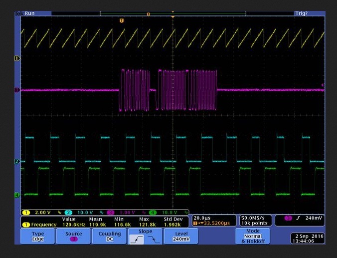
    In the oscope plot below:

    Channel 1 is the UC1846 “A Out” pin, Pin 11

    Channel 2 is the UC1846 “B Out” pin, Pin 14

    Channel 3 is the UC1846 “V+” error sense pin

    Channel 4 is the UC1846 “CS+” current sense pin


    A couple things to take into account in these scope plots:

    1)      Pin 11 timing is not controlled in the circuit.  That is, its “on time” will be at the maximum time, based on the oscillation frequency.  Therefore, the dead-time would be the time from Pin 11 (Channel 1) going low to Pin 14 (Channel 2) going high.  It’s hard to get specific numbers from this scope plot, however, it appears to be about ¼ of the time between each “dot” (2us between each dot), or ~300-400ns.  Per the UC1846 datasheet, the dead-time should be ~145ns based on 1000pF/15.8Kohms.

    2)      The noise seen on the V+ pin and CS+ pin may well be an artifact of the test lead wires (coupling effects) that were attached to the UUT to monitor these points.  These wires were ~5’ long

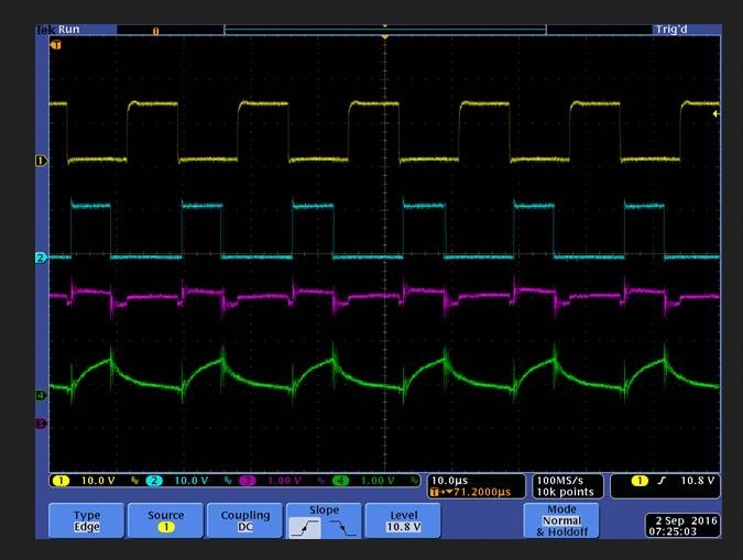
    The below oscope plot shows the CT voltage.  Again, this is with 1000pF for CT and 15.8K for RT.:

    Channel 1 is the UC1846 “CT”, Pin 8

    Channel 2 is the UC1846 “B Out” pin, Pin 14

    Channel 3 is a signal external to the UUT used to trigger the oscope, a 1553 signal in this case.

    Channel 4 is the UC1846 “A Out” pin, Pin 11

    I have asked the customer to zoom in so the dead time could be seen better in the scope shots. I will reply back once they are available.

    There seems to be the be some dead-time after BOUT goes LOW, but I thought that the dead-time usually occurs between AOUT going LOW and BOUT becoming active.

    Please let me know what you think after viewing the scope shots.

    Thanks for your help with this!

    Richard Elmquist
  • Hi Richard,

    The deadtime calculated from the formula (145* Ct) is the SYNC (pin10) pulse width, see Figure 4 in the datasheet. Please measure the SYNC pulse width.

    Regards,

    Bosheng Sun 

  • Bosheng,

    Thanks for your response!

    I will have them measure this and I will respond back if they have any further questions.

    Thanks again.

    Richard Elmquist