This thread has been locked.

If you have a related question, please click the "Ask a related question" button in the top right corner. The newly created question will be automatically linked to this question.

ucc29811 ac/dc unstable when load is connected

Other Parts Discussed in Thread: UCC28911

Hi there,

I hope someone can advise me regarding to couple of issues that I am having with UCC28911 that I have designed.

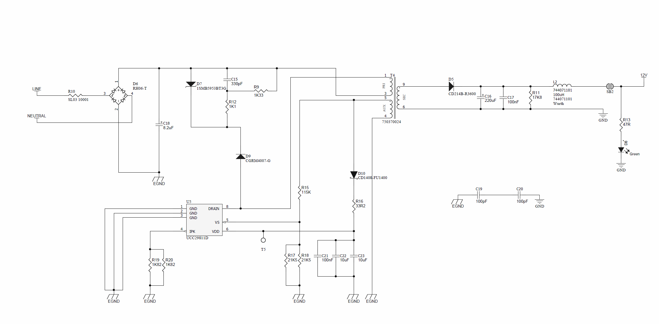
Current design uses Universal AC input and generates 12V on the secondary side of the transformer. Due to some height and width restrictions of the mechanical design, I have used the 750370024 transformer from Wurth.

The problem is when I turn the power on from the mains, I do get the 12V ~13V coming out from the secondary side of the transformer and seems to work fine up to this point. I have a switcher that get connects to 12V power rail to generate 3.3V for micro-controller. I do get the 3.3V coming out from the switcher as well.

But when I connect my external microcontroller board to the 3.3V rail, UCC28911 resets with varying time. When I first plug it in, it works for good few minutes and stops and starts to reset. Any idea about what might be the problem is really appreciated. 

I am attaching a schematic as well, hope to hear some usefull response to help me to debug the issue

  • Hi Mustafa, the UCC28911 does have several fault protections as detailed in section 9.3.7 of the datasheet. I would check first what is happening on the output voltage, Vdd voltage and Ipk pin of the IC and see if any of the faults mentioned in the datasheet are being tripped. If the unit is going into constant current mode it may be resetting because the Vdd rail falls too low for example. 

    Thanks

    Billy 

  • Hi Billy,
    Thanks for your answer, with no load, I have connected the multimeter to VDD rail and measured the voltage on the VDD rail.
    When there is no load the Vdd value satisfies the offline converter turnon voltage and converter switches and powers the 12V to 3.3V switcher with no issue.
    The problem occurs when the load assigned to the 3.3V rail. VDD for the offline converter generated from the auxiliary winding goes below offline converter turnon voltage, and stops switching. I have not figured out nor understand why would the AUX winding voltage drops when there is not much of a current being drawn out from the secondary side of the transformer.

    Hope to hear any suggestions from your experience regarding to this issue. I am starting to think that the transformer is not right for the job?

    Thanks
    Mustafa
  • Hi Mustafa,

    I would suggest that you follow the design example in the datasheet to calculate what inductance is required for your design.

    You also need to make sure that your transformer can handle the output power, essentially that for your chosen core, L* I = n*B*A.

    An easier approach if you are not familiar with the design equations may be to use Wurth's Smart Transformer Selector to select the right part.

    For an explanation of the design consideration for a flyback transformer see the following link "ecee.colorado.edu/.../Ch14slides.pdf"

    Hope this helps.

    Thanks

    Billy

  • Hi Billy,
    Thanks for the link, I did have a look the inductance value from the datasheet and calculations. It seems like transformer should be capable of handle the output power.

    Looking at the transformer auxiliary winding, I should have enough power to supply the offline converter and I did measure it with the multimeter and I saw that it is achieving the VDDon voltage on the auxiliary pin thats get connected to IC as well.

    I was checking my layout for this design and realised that, track width is little thin (0.254mm) from R16(I am using the 0603 size footprint for this resistor) to VDD pin.

    Do you think this would affect the operation of the off-line converter? which would affect power delivery to the IC!
  • No really no.

    When you say that the Vdd voltage is high enough, do you mean at no load, or when you connect the load.

    Under the operating conditions that are giving you problems I would look at the Vdd voltage and the Ipk voltage to see if the core is saturating.

    Note that the equations in the datasheet help to calculate the required inductance but not the required core size to deliver the power. The power handling of the transformer is down to core size, air gap and number of turns, not just the inductance.

  • Hi Billy,

    sory for the late response, I have been try to find, what might be problem for the last couple of days. One thing came to my attention and I have not tested it yet, but before i made the test, I wanted to double check this with you as well.

    I think the issue I am having is related to Voltage Sense resistor values. Looking at the transformer Auxiliary winding, transformer Auxiliary winding should be capable of sourcing the 16V. When I calculate the Voltage on the voltage divider, I am actually getting 2.52V, which is way below the Regulating level of the Vvsr. 

    I think this might be one of the reason, why my converter is constantly restarting or going into fault mode and stops operating.

    On my previous tests, while I was monitoring the Auxiliary winding voltage, i did see values over 16V with the multimeter and I think this was causing the voltage drop on the secondary winding and also the auxiliary winding was saturating.

    Hope to hear your advise on this

    Regards

  • any thoughts if this will affect the operation of UCC28911?
  • Mustafa, the IC regulates the Vs pin to 4.05V. It will keep driving up the output voltage until the Vs pin gets to this level. From the values given in your schematic and the turns ratio on the datasheet of the transformer this equates to a bias voltage of approimxately 4.05V / R17||R18) * (R15 + (R17||R18)) = 4.05V / 10.75 * 125.75 = ~ 46V. And an output voltage of ~ 46/8*6 = ~ 35.5V. According to the datasheet the Vdd pin has a nominal clamp voltage of 28V and an minimum clamp voltage of 26V. Exceeding this voltage will cause the IC to go into fault mode and restart.

    Are you sure the Vdd voltage is not exceeding this level. You will need to look at the waveform on the pin with an oscilloscope, not a multimeter to be able to tell accurately.

    Thanks

    Billy

  • Hi Billy,
    Thanks for your response, R18 is DNP on that circuit. I forgot to mention that. So I only populate R17. so the etimated bias voltage value should be 25.7V which is close to clamp voltage of 26V.

    I have change the R15 to be 100K ohm and R17 to be 34K ohm at the moment.
    So now I should get ~16V on the bias voltage and I should get ~12V on the output !!

    Which is what I am trying to achieve.
    Let me know if that sounds correct now.

    At the time of the first test we did not have oscilloscope in the office, we have recently purchased a new one and we are waiting for it.

    Thanks
    Mustafa
  • That sounds better alright.
  • Hi Billy,

    I have made those changes on to the board.

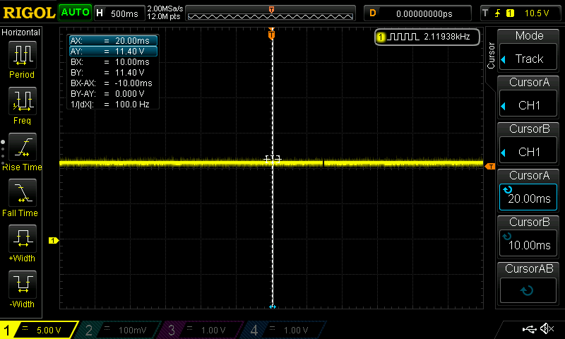
    When I turn the board on i get 11V coming out from the secondary winding of the transformer.

    Switcher connected to the secondary side after the inductor generates the necessary 3.3V nicely as well.

    Image below is the secondary winding connected to switcher and works fine.

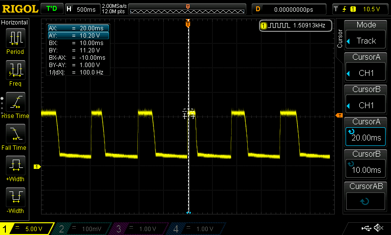
    but when I connect the load to the 3.3V generated from the switcher, secondary winding voltage response is shown in below image

    I have not checked the voltage on the Vdd of UCC28911 just yet with the oscilloscope, I am not quite sure if I connect my oscilloscope ground probe to EGND or GND on the circuit.

    Assuming the calculations are right, when I measure the voltage on the Vdd pin, I should not get values higher than 16V?

  • You will probably see some spiking above 16V, but the steady state voltage of the winding should be approximately 16V during the secondary conduction interval.

    You should connect the scope ground to EGND in your schematic above.

  • Hi Billy,
    Connecting the EGND to scope ground caused a short, blew the fuse R28 on the board. I will replace the fuse on the board but I am not quite sure how to probe the VDD pin with oscilloscope when ground probe is not connected ?
  • Hi Mustafa, I don't see R28 in the schematic but anyway.
    I assumed that you're input voltage was isolated through an isolation transformer but I see know that that is not the case. The scope ground is connected to earth so connecting the earth to EGND in the circuit shorts out the diode bridge and blows the fuse. It is difficult to probe the primary side nodes without an isolataed input voltage source.
  • unfortunately, we do not have the isolation transformer, also the scope is not battery powered as well.