This thread has been locked.

If you have a related question, please click the "Ask a related question" button in the top right corner. The newly created question will be automatically linked to this question.

UC2846: Parallel operation of UC2846

Part Number: UC2846
Other Parts Discussed in Thread: OP27

Hello,

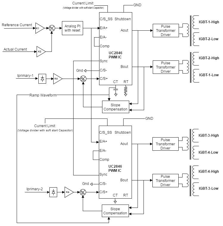
I am working on building a constant current DC power supply. It consists of two full H-bridge DC-DC converters feeding two HF transformers. The secondary side of HF transformers are connected with diodes and outputs are paralleled to provide total output current. I'm using two UC2846  peak current mode control IC to regulate the power supply output. I'm facing problem when paralleling two PWM ICs, one of the PWM IC outputs (Aout, Bout) goes low. The control configuration is shown in image below. (IGBT-1,2,3,4 are IGBT modules that contains two devices in them, high side and low side. IGBT-1,2 are for Inverter-1. IGBT-3,4 are for Inverter-2) The following points are significant in the design. 

1) Shutdown feature is not used (Pin 16 is connected permanently to GND)

2) Timing capacitor pin (Pin 8) in slave PWM IC is connected to GND.

3) Sync pin (Pin 10) of both master and slave PWM IC are connected together.

4) Error amplifier in UC2846 is used in unity gain configuration ( Pins 6 and 7 are shorted) in both master and slave PWM ICs.

5) Identical slope compensation is used for master and slave PWM ICs (Ramp waveform available in CT pin of master is used for slope compensation in slave)

6) External analog PI using OP27 op-amp is used instead of using E/A+, E/A-, Comp pins to construct PI as suggested by datasheet.

The design works fine with single H-bridge inverter but when two inverters are operated in parallel one of the inverter PWM pulses goes low.

I have two questions.

1) I would like to know if the way two PWM ICs are paralleled is correct? or Is there any other way to parallel.

2) Connecting two Sync pins to have a unified clock reference is sufficient or any external circuit is recommended to connect two Sync pins?

Any answers /  suggestions?

I'm curious to know about using this UC2846 PWM IC to parallel two full H-bridges. So kindly avoid suggesting to change power topology or of that sort!

Thanks,

Mervin.

  • Hi Mervin,

    I have requested an AE to help with your question.
  • Hi Mervin,

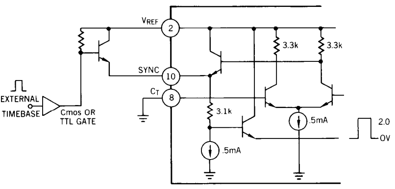
    Synchronization of one or more devices to either an external time base or another UC2846 is accomplished via the bi-directional SYNC pin. To synchronize devices, first, CT must be grounded and RT should pull up to VREF to disable the internal oscillator on all slaved devices. Second, an external synchronization pulse must be applied to the SYNC terminal. This pulse can come directly from SYNC terminal of a master or alternatively, from an external time base as shown below.

    Thanks,

    Oliver

  • Hi Oliver,

    Thanks for responding. I'm clear about connection of Sync pins for parallel operation.

    Do you have any feedback about parallel operation of two UC2846 with their Error Amplifiers (pins 5,6,7) configured in unity gain (as illustrated in my question above)?

    I noted from datasheet that the recommended connection as below one which deviates from my configuration. I prefer to use external op-amp based PI regulator to feed pin 5 (E/A+) and operate the internal error amplifier (of UC2846) in unity gain (by shorting 6,7 pins). So to parallel two current mode controllers I have shorted E/A+ (pin 5) of both PWM ICs in my configuration.

    Is it correct and serve the purpose?

    Thanks,

    Mervin.

  • Hi Mervin,

    I think you'd better disable the oscillator and error amplifiers (CT grounded, +E/A to VREF, -E/A grounded as above diagram shows) of the slave module, and connect SYNC and COMP pins of the slave to the master controller respectively, because the characteristics of internal error amplifiers may not completely consistent between the master and slave.

    Thanks
    Oliver
  • Thanks for the suggestion Oliver.