This thread has been locked.

If you have a related question, please click the "Ask a related question" button in the top right corner. The newly created question will be automatically linked to this question.

UCC256301: UCC256301 start-up

Part Number: UCC256301
Other Parts Discussed in Thread: UCC256303, UCC256304

Hello!

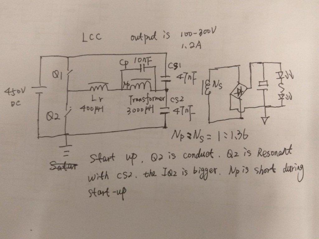
During start up, ucc25630 LO PIN is keep high for the CBOOT capacitor charge,if we use the symmetry half-bridge,which have two resonant  capacitors,during start up,the low side mosfet is constant conduct;

the current flow on the low side mosfet is very bigger,The Lr transformer will be saturated.which will cause  the mosfet break down,What is the solution to this problem。Do you have a demo board which design

by  LCC

.

     Thank you!

  • Hello,
    We are looking at your question and will reply you as early as possible.

    Best Regards
    Frank
  • Hello,

    Q2 will not be damaged, and transformer will not be saturated, this is because:

    1, There is only 1 wide PWM pulse during start up, it is about 260uS. After that the pulse width becomes normal.

    2, The resonant capacitor CS2 is only 47nF, not much energy stored there.

    3, The resonant inductor Lr will limit the current.

    We have LLC EVM available, you can order from TI website.

    Regards,

    Bosheng

  • Hello!
    It's ok in general applications for the frequency is 80-150kHZ,If the normal operation frequency >300KHZ, Lr will less than 50uH.The peak I(Lr) is very large during start-up and the current is small when normally operation.Lr is very difficult to design,high saturation current is required.For example the peak I(Lr) is 10A during start up,but at normal operation is just 2A.The Lr needs to be designed according to 10A
  • Is there anyone who can help answer this question?
  • Hi,

    What is the slew rate of the input voltage?

    Best Regards,
    Ben Lough
  • Hi,

    Apologies, I misunderstood your original question. If you are seeing a large current during the charge boot state, You could try a smaller resonant capacitance.

    Best Regards,
    Ben Lough
  • I'd suggest you move to a single resonant capacitor - 2 x 47nF caps in the CS2 position. This is a widely used variation and there are no differences in switching behaviour between the single ended and the split resonant capacitor variations. It should be as simple as moving your high side Cr and putting it in parallel with your low side Cr - no other changes are normally needed.

    Regards
    Colin
  • Thank you, Colin!

    I have another question to all.
    UCC256301 is supplied by a auxiliary power supply,the voltage is 15V constant, which is connected to VCC via a diode,
    Because the IC start up voltage is 25V,so HV pin JFET will turn on during the start up period.
    I use FB pin for system on/off control, if I pull the FB pin down to ground, the system will be off, then what will the current of the VCC pin be?
    Then if I release the FB pin to be open, will the HV pin JFET turn on again?
    Could you please explain the difference between,ucc256301,ucc256303 and ucc256304
    Beside of the difference of HV star-up,X-CAP discharge, any others for ucc256303 ?
    ucc256303 can be used in DC input power supply system and the other two are not?
  • Hi,

    When the FBreplica is less than the burst threshold, the LLC will cease switching. The VCC supply current should be less than ICC_run. The HV pin JFET will turn on if VCC is below the VCCRestartJfet threshold which is 10.5V.

    UCC256301 and UCC256304 are primarily targeted for AC/DC systems becuase they include HV startup from the AC line and X-cap discharge. The primary difference between UCC256301 and UCC256304 is the bulk startup threshold which is 3V in UCC256301 and 1.06V in UCC256304. The other difference is the overvoltage protection threshold which is 4V in UCC256301 and 5V in UCC256304. I would not recommend using either of these for DC/DC because even if you connect a DC voltage to the HV pin, the device will not detect any zero crossings and try to execute an x-cap discharge.

    UCC256303 is does not include HV startup or x-cap discharge and is meant to be used with an auxiliary supply. The VCC input range is slightly larger for UCC256303 as well (can be as low as 11.25V).

    Best Regards,
    Ben Lough