This thread has been locked.

If you have a related question, please click the "Ask a related question" button in the top right corner. The newly created question will be automatically linked to this question.

UCC28700-Q1: Need help reviewing the design including transformer

Part Number: UCC28700-Q1

Hello,

i need help reviewing the design of the flyback supply with 2 secondary outputs.

Currently i have a problem where the VDD would ramp to around 20V then the device restart itself. I can also hear the audible clicking noise from the IC when the device restart.

I use WEBENCH to come up with the design. My design input are the following

  • Vin = 80V - 265VAC
  • Vout = 12VDC
  • Iout = 2A

What i did added to the design is one more secondary to be able to have both isolated and non-isolated 12V output.

Here is the design result from WEBENCH

What i have differently in my circuit, is the my D2 is a standard diode (FS8J) and not schottky diode. But i don't think this is the problem.

My assumption of the problem was with the transformer winding. I did recheck the transformer specification with the datasheet equations, and the turn ratios came to the same value as WEBENCH design.

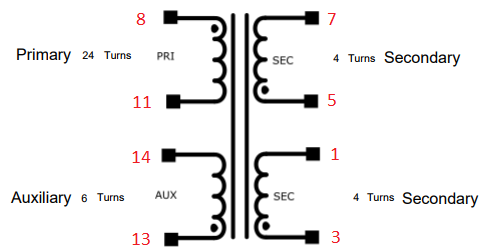
I hand-wind the transformer using this configuration on this bobbin from TDK (B66230A1114T001).

I measured no voltage on the auxiliary winding. I believe this is because the device is not switching. The input voltage during testing were between 230-240VAC, rectified was around 330VDC to the primary.

The schematic is attached.4048.Schematics.pdf

  • Natthapol,

    Thanks for your interest in TI here.

    To better understand what's going on could you provide transformer inductance(primary magnetizing), and waveforms showing Vcc, DRV, and the aux winding waveform at the transformer? (Preferabley together on the same scope shot if possible). If we get all those signals we should be able to understand how the controller IC itself is behaving on your board.

    Additionally can you share the full Webench design document that prints out all specs and values?

    Webench doesn't support multiple outputs yet so if you did not do already I suggest to be sure you add up the total output power and use that to calculate as if it was a single output design with the total output power of your full design. That will ensure the peak current and magnetizing inductance are more realistic.

    The diode differences you mentioned may actually impact this as the turns ratio and regulation point do need to take into consideration the diode drop.

    If you want even more flexibility to look at the details of the design procedure beyond Webench you can also run your design through our excel design calculator here:

    That will allow you to see more on the impacts of each component selection. You would still need to add the total power and use that in the calculations as the calculator is focused on a single output design.

    Additionally, since it is the weekend and most of our applications engineers will not be working again until Monday, you may consider to review the following debug resources we have available:

    I hope we can resolve this with you very soon. Let me know if you have any questions on what I've suggested.

    Regards

    John

  • I have to respin the board to be able to give those measurements from oscilloscope. I will post an update here once the measurement is available.
  • Ok; thanks. Let us know.

  • With +12VP non isolated the tricks in the blog post can not be used. Could +12VP be taken from the aux winding (LDO)?
  • Hi Eric,

    this is actually seems like good trick, I have never thought of doing that before. Let me think this through first, it seems like a good idea.

  • I understand that the auxiliary voltage is taking from the secondary winding during MOSFET off phase.

    The information in the datasheet, also show that the auxiliary winding voltage sometime goes below 0V, during the energy transfer state. I think the LDO on auxiliary winding method will have a problem here.

  • Yes, but you use a diode and capacitor to rectify the voltage before the LDO. Just like D3 and Cdd in your schematic creates Vdd for the IC.

  • Hello John,

    i have replace the diode on the secondary side with low Vf Schottky and done some measurements but the isolation transformer that i was using, decided to stop working. So i will give you what i have from the last measurement session until the replacement transformer arrive.

    I still see no voltage on auxiliary winding, not even a slightly move. On the secondary side however, does rise to about 0.5V then drop back to 0V.

    Transformer
    Inductance (primary) 1.659mH
    Leakage Inductance (primary) (tie aux, tie both secondaries) max. 20µH
    DC resistance on all windings max. 0.1Ohm

    The measurement was done with no load on the secondary side, but there is a 154Ohm resistor across each secondary. I also could not get all the measurements on the scope shot.

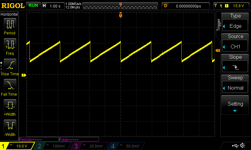
    VDD

    VDD ramp to 21V and restart.

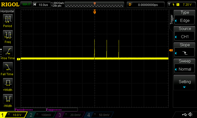
    DRV

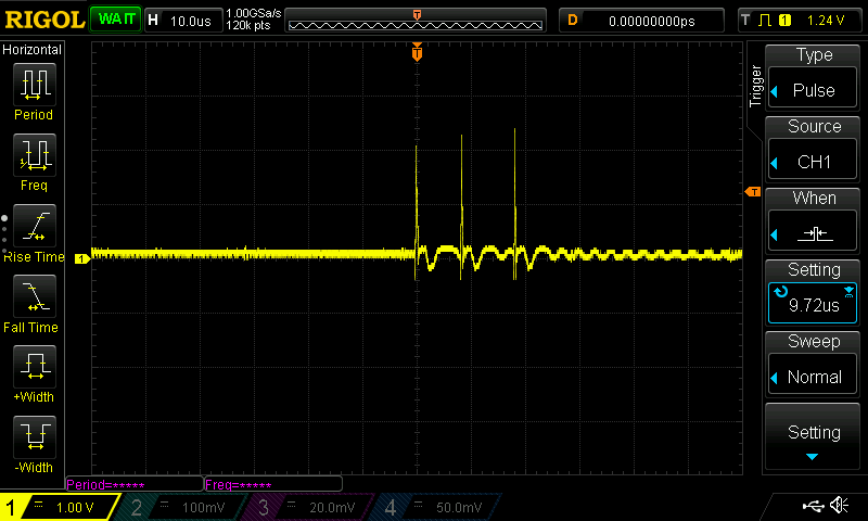
    DRV sends 3 pulses

    I have also attach the WEBENCH design report.webench_design_4899890_28_767448723.pdf

  • here are some more measurements

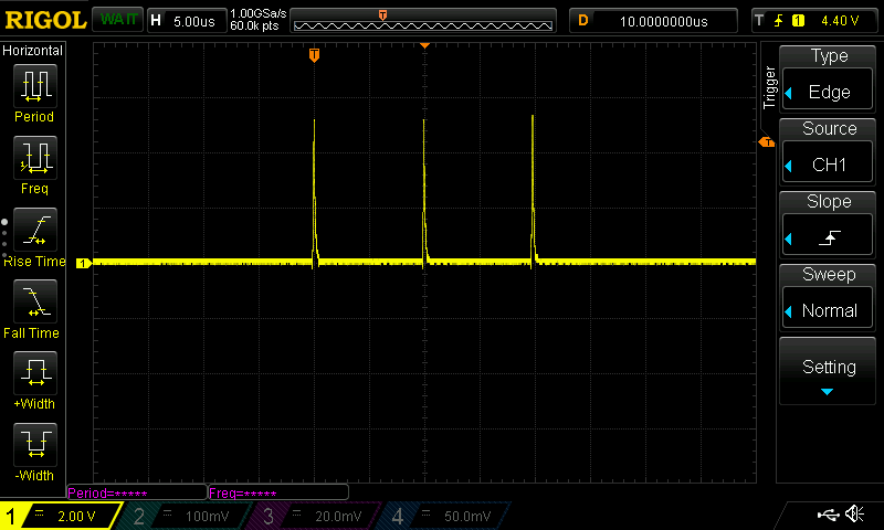
    CS pin

    VS pin

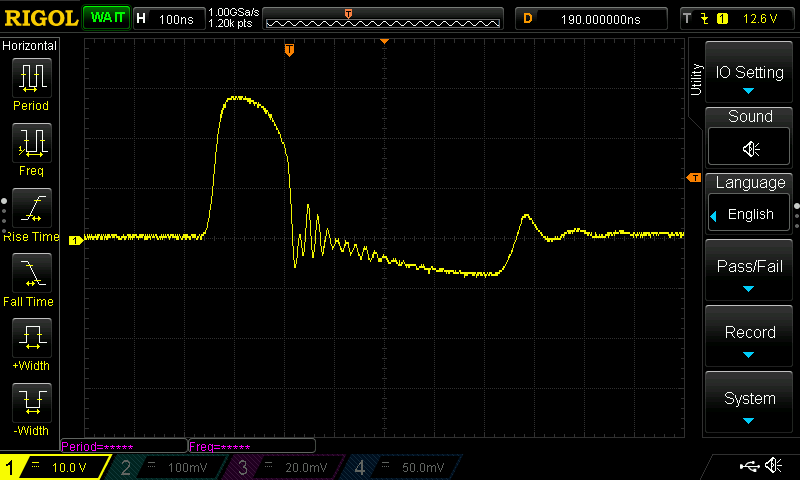
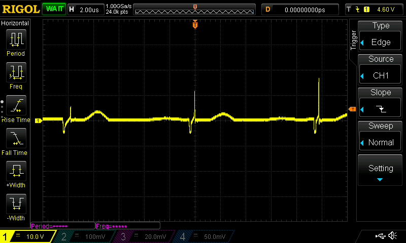
    Auxiliary winding at transformer pin (1 switch pulse)

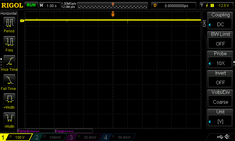
    Primary winding = ~340V

    Isolated secondary winding at transformer pin

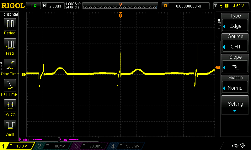
    non-isolated secondary winding at transformer pin

  • I managed to get the part to work correctly, but i get audible buzzing noise when the converter operating. Is this normal? It sounded like fast switching noises.
  • Natthapol,

    Sorry for the delay in responding with the US holiday season. Have you made any progress with this or you are still struggling with audible noise?
    If you still have audible noise, be sure that you designed the magnetizing inductance so that you are operating at maximum frequency possible at maximum load. this ensures that you are much lower power by the time the converter crosses through audible switching frequencies. Other options may include varnishing the transformer if that is the component causing the noise.

    Regards,
    John