This thread has been locked.

If you have a related question, please click the "Ask a related question" button in the top right corner. The newly created question will be automatically linked to this question.

UCC28740: Don't see any DRV pulse at start up

Part Number: UCC28740

Hi

i am using the UCC28740 for my LED power supply design. I have designed the circuit using the excel sheet tool.

When I power my IC, I don't see any DRV pulses at all. Not even 3 pulses at start up. I have tried powering the IC both from Aux winding and from an external power supply, but no luck so far.I have also tried increasing and reducing the Vdd capacitor but irrespecitve of the capacitance I always see my Vdd continuously pulsing between 7V and 21V.

Any help will be highly appreciated.

Thanks.

  • Rachit,

    Thanks for your interest in TI. This is a very popular controller. Sorry to hear you're having some trouble here.

    During startup the vdd cap is initially charged through the HV pin. Once Vdd is above 21v you should see 3 pulses from drv. From there, if there are no fault at Vs, CS, FB, the controller starts its normal startup sequence.

    Can you provide your schematic and waveforms of your aux winding, CS, drv, Vdd?

    Have you changed out the IC to verify ucc28740 wasn't damaged?

    Also, although I'm assuming you are using optocoupler feedback here as a flyback this app note may still be useful as many of the protections and common debug are the same:

    Regards

    John

  • UCC28740 Design.zip

    Hi John

    Thanks for replying to my issues. I appreciate your help.

    I was able to get 3 pulses at DRV pin but after that the controller shuts down and the Vdd discharges from 21.6 V to 7.1 V and then charges again and then when it reaches 21.6V again I see 3 pulses.From what I understand this is because of some fault condition been hit. I have check all the possible fault conditions but wasn't able to figure out what exact fault is been generated.

    I have attached the schematics, Wave-forms and the design tool I have used for this design.

    It would be really helpful if you can take a look at these and point me in the right direction to resolve this problem.

    Another observation I made was as I increase in Input Voltage the pulse width of the second pulse reduces, I am not sure if it is expected behavior.Also, There is a miller plateau in the DRV waveform just for the first pulse(Which Reaches 14V) but the next two pulse don't have the miller plateau and they only go to 5V peak.

  • Hello Rachit,

    The VS pin is sensitive to probing and can trigger and under voltage fault if you probe it directly. It you want to detect for faults you should probe the aux winding instead of the VS pin.

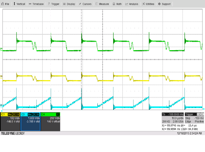
    From the waveforms that you have the aux wining polarity does not look correct. When the FET is on it should be negative and not positive.  I am curious if your issue is because your transformer polarities are incorrect.  I would double check that first.

    The following waveforms were taken from a DCM flyback at full load similar to the one that you are working on. CH4 = FET Drain, CH1 = Aux voltage, CH3 is the CS signal.   This should help to show what the polarity of the transformer should be.

    Regards,

    Mike

  • For some reason this waveform did no post.