This thread has been locked.

If you have a related question, please click the "Ask a related question" button in the top right corner. The newly created question will be automatically linked to this question.

UCC2897A: Self synchrounous rectification at secondary side.

Part Number: UCC2897A
Other Parts Discussed in Thread: PMP8944, LM5026

Hello friends,

I have a doubt regarding Active clamp forward converter with synchronous rectification at output side circuit.

My input voltage spec is 18Vdc-54Vdc

Output: 24V@5A & efficiency > 90%

I am planning to use UCC2897A as my pwm controller with self driven synchronous rectification at output side.

I have seen a reference design from TI that is PMP4844. In this design self synchronous rectification is not used. Is there any problem in using self synchronous rectification for this spec?.

Regards

Aneesh

  • Hi Aneesh,

    Thanks for your interest in UCC2897A. You should not have a problem implementing self driven synchronous rectification in this design. Your efficiency will not be as high however. This application note provides further detail on the tradeoffs between self driven and IC driven synchronous rectification:

    Best Regards,

    Ben Lough

  • Hi Ben Lough,

    Thanks you for your valuable comment. I just went through the attached document. I have some more quires.

    1. Is it possible to get greater than 90% efficiency at 70V input with self synchronous rectification?.

    2. In PMP8944 reference design TI is getting more than 90% efficiency but it is at 30V input max. So if the same PMP8944 board if i redesign for 70V input i will get only 82% efficiency(as per fig 27 in the attached document) max right?

    Regards

    Aneesh

  • Hi Aneesh,

    It is possible to get >90% efficiency at 70V input with self driven synchronous rectification but could be challenging. Here is an example of active clamp forward design that achieves ~90% efficiency at 72V:www.ti.com/.../PMP7032

    It is difficult to say with absolute certainty how much your efficiency would drop if you implement self driven synchronous rectification and redesigned for a higher input voltage but you will have slightly lower efficiency at the higher input voltage .

    As a reference, here is a 24V, 3A active clamp forward design using self driven synchronous rectification:www.ti.com/.../PMP20878

    Best Regards,
    Ben Lough
  • Hi Ben,

    Thanks for your feedback. It really helped me.

    Regards

    Aneesh

  • Hi Ben Lough,

    I have a doubt regarding LM5026 Evaluation board. In LM5026 Evaluation board the output current is limited to 33A(Hiccup over current).

    There is no current sensing at output side.Then How this current limit achieved in LM5026 Evaluation board?. Which component in the schematics decides 33A current limit.

    Regards
    Aneesh
  • Hi Aneesh,

    current sensing is accomplished through the CS pin on LM5026. Its looking at the primary side current through a current sense transformer and enabling cycle by cycle limiting when the pin is >500mV.

    This works as an output current limit because the primary side current is proportional to the secondary side current. The exact relationship is derived in section 11.1.1 of this user's guide:www.ti.com/.../slyu036.pdf. There is some variation in the primary side current from min to max input voltage but the variation is small enough to provide a stable output current limit of ~33A. As a check, you can plug the LM5026EVM parameters into power stage designer to see how much the primary side current varies across the input voltage range:www.ti.com/.../POWERSTAGE-DESIGNER

    Best Regards,
    Ben Lough
  • Hi Ben Lough,

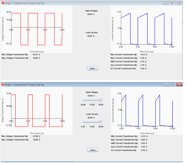
    I have checked the input current in powerstage designer for the LM5026EVM spec from 36V to 78V input and 3.3V/30A output. The rms input current is varying from 2.54A to 3.74A from 36V to 78V for 30A. But still the EVM detecting overload at 33A output current. Could you please explain this?


    Regards
    Aneesh
  • Hi Aneesh,

    Could you do me a favor and post a screenshot of your inputs in the power stage designer GUI?

    Best Regards,
    Ben Lough
  • Hi Aneesh,

    The overcurrent limit is implemented as a discrete voltage threshold on the CS pin and the max voltage on the CS pin during one switching cycle occurs at the maximum of the primary side current. Because of this, the overcurrent protection on LM5026 looks at the peak primary side current instead of the RMS primary side current.

    From the screenshots you shared, the difference between the maximum primary side current at Vinmin and Vinmax is 190mA. You will see a little variation in the overcurrent trip threshold because of this but overall the overcurrent threshold will be fairly consistent across the entire load range.

    Best Regards,

    Ben Lough

  • Hi Ben Lough,

    The over current detection scheme in LM5026EVM is based on the peak current not as per the rms current right?. If so, the explanation looks fine for me.

    Thanks for your reply.

    Regards

    Aneesh

  • Hi Ben Lough,

    The over current detection scheme in LM5026EVM is based on the peak current not as per the rms current right?. If so, the explanation looks fine for me.

    Thanks for your reply.

    Regards

    Aneesh
  • Hi Aneesh,

    Yes, the over current protection scheme is based on the peak current.

    Best Regards,

    Ben Lough

  • Hi Ben Lough,

    I have one more doubt regarding toroid transformer. I feel your explanations are quite convincing for me that is why i am asking you doubts personally here. I want to replace the transformer in LM5026EVM with a toroid core transformer. I rarely seen somebody using a toroid transformer for DC-DC converter. Even in TI Reference design or evaluation board none of the design has done with Toroid core transformer. Could you please explain me why nobody preferring toroid core transformer?

    Regards

    Aneesh
  • Hi Aneesh,

    A magnetics vendor will be able to answer your question in greater detail but in general, size and cost tend to be prohibitive factors. You are restricted to an "O" shape structure which utilizes much more space than an E core/bobbin equivalent. Winding a toroidal transformer is more difficult so there is some added cost in the manufacturing process. For reference take a look at this application note. You will find some information about toroid transformers on page 43:www.ti.com/.../slup132.pdf

    Best Regards,
    Ben Lough
  • Hi Ben Lough,

    Thanks for your valuable answer. I have still some more doubts regarding the gate driving capacity of the LM5026. The OUT_A pin of LM5026 is having 3A driving capacity. what is the criteria for selecting the gate driver source and sink current capacity?. Can i use a 1A current rated driver in stead of 3A for the same LM5026EVM? or suppose if the current rating of LM5026 was 1A whether i need to use any extra driver for the same application?. Which parameter in the circuit decides the driving capacity of the PWM controller IC.

    Regards
    Aneesh
  • Hi Aneesh,

    The gate drive source and sink capability is determined by the internal gate driver for OUTA and OUTB. The source/sink capability of the internal drivers are fixed. Typically you want more (not less) drive capability to guarantee fast gate transitions to limit switching losses. An external gate driver is sometimes necessary when you operate at higher switching frequencies or you have larger gate capacitance because you have multiple MOSFET's connected in parallel.

    Best Regards,
    Ben Lough
  • Hi Ben Lough,
    Thanks for your reply. But i just want to know the design equations for the gate driver capacity. Why 3A driver selected in LM5026EVM?. Cant i use a 2A driver? or what is the minimum driver current capacity required?.

    Regards
    Aneesh
  • HI Aneesh,

    3A is an internal characteristic of the gate driver in LM5026. It's not a selectable metric but simply what the internal driver is capable of delivering. There is nothing preventing you from using an external gate driver with LM5026 but I would caution using a gate driver with lower source/sink capability would not benefit your design (typically an external gate driver is used if the gate driver on the controller is not capable of sourcing/sinking enough current).

    The required driver current capacity depends on your switching frequency and how much gate capacitance your MOSFET's have. You want enough drive capability to guarantee dead time between your switching pulses.

    Best Regards,

    Ben Lough