This thread has been locked.

If you have a related question, please click the "Ask a related question" button in the top right corner. The newly created question will be automatically linked to this question.

UCC2897A: Timing Equations

Part Number: UCC2897A

Hello,

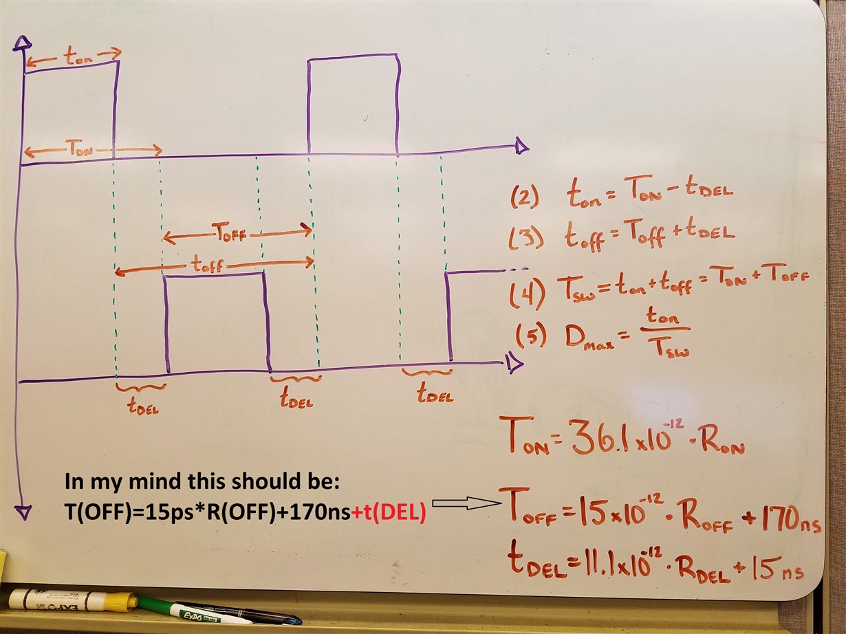
Can you help me understand these equations in the datasheet (Eq.1-5)?

  1. Why does T(ON) get T(Del) subtracted from the on-time set by R(on), while T(OFF) has T(Del) added to the off-time set by R(off)?
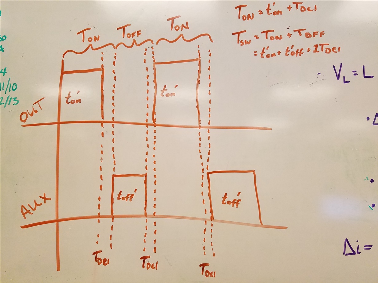
  2. Due to the opposite polarity mentioned above, equation 4 suggests that the switching frequency is independent of the delay time T(del). In my mind the switching period would be t(on)+t(off)+2T(del). What am I missing? (Picture Below)

Thank you!

Ryan B.

  • Hi Ryan,

    In any switching converter the on time refers to the total time the main switch is conducting and the off time refers to the total time the main switch is off.
    So ton in the data sheet refers to t'on in your sketch and toff in the data sheet refers to t'off +2T(DEL) in your sketch.

    I think the confusion arises because the data sheet definition of ton and toff is not the same as T(ON) and T(OFF) in your sketch.

    Regards

    John

  • Hi John,

    Okay that definitely helps clear some things up. 

    However, I'm still confused on how the switching period is independent of the delay.

    If I substitute datasheet equations (2) and (3) into equation (4), I see that the switching period is only dependent on R(on) and R(off). If I fixed those two resistance, but varied R(del), shouldn't my switching period grow/shrink as the delay grow/shrinks?

    I hope that makes sense.

    Regards,
    Ryan Bishop

  • Hi Ryan,
    Your timing diagram is not correct.
    Please see SLUA535 for correct timing.
    This is a fixed frequency controller. You can set the operating frequency and the overlap time but the operating conditions and control loop will set the on and off times

    Regards

    John


  • Hi John,

    Okay thank you, I'll have to spend more time studying up on that app note.

    One more questions on a similar topic. The customer wants to take the frequency/duty cycle tolerances into account for this design. In the datasheet we specify the min/nom/max frequency and DC as follows:

    Frequency (kHz): 225/250/270
    Duty Cycle (%): 66/70/74

    However, those are when R(on)=R(off)=75kOhm. How can we translate these tolerance to designs using different resistor values? Will the frequency always be within +20kHz/-25kHz and duty cycle within +/-4%? Or is it more accurate to think of the tolerances as a +/- percentage of the nominal value?

    Thank you!

    Ryan B.

  • Hi John,

    Just wanted to check in on my follow up question.

    Thank you!

    Regards,
    Ryan B.
  • Hello Ryan,
    This is a new question and really requires a new post to be opened but I will continue with an answer to your question.

    Like all of TI PWM controllers the min and max values of frequency are characterised over temperature at one chosen switching frequency.
    It would really be impossible to characterise the part over all possible switching frequency.
    With values of RON and ROFF equal to 75k the switching frequency varies from 237kHz to 265kHz.
    So it has a tolerance of 6%.
    The switching frequency can be varied according to Fig 9 in the data sheet and the typical range is about 30kHz to 2MHz.
    Within this frequency range the user can expect to achieve a tolerance of 6%.
    But as part of any new product qualification process the end product needs to be tested to ensure it meets its design requirements.
    Regards
    John