This thread has been locked.

If you have a related question, please click the "Ask a related question" button in the top right corner. The newly created question will be automatically linked to this question.

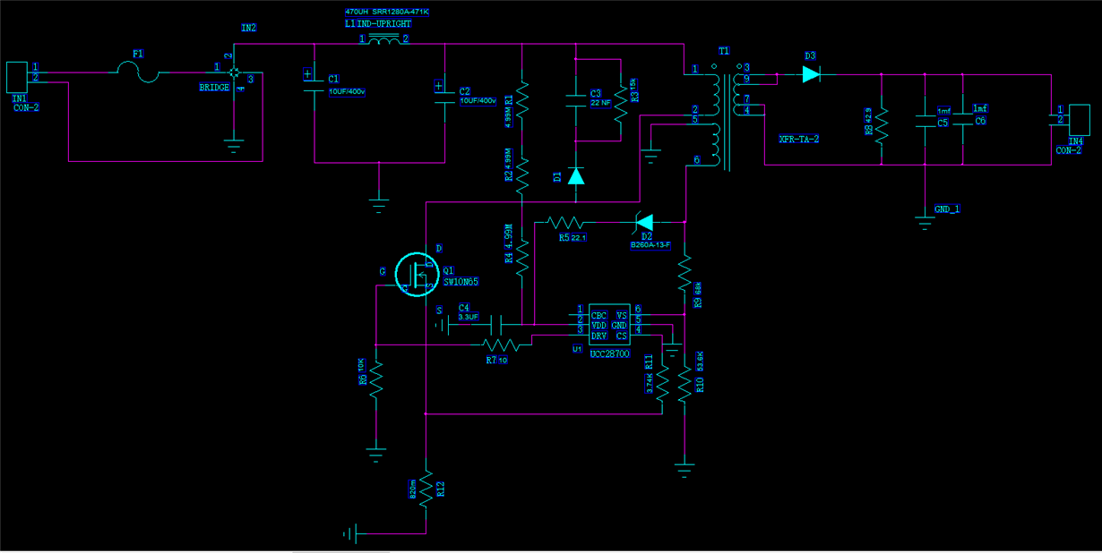
UCC28700: i MADE a sch of it with the UCC28700 ,the input voltage is ac 220v 50hz , the rectifier bridge , diode D1 and the mos tube WILL be damaged when we power on the ac. can you help us to analyze this problem.the sch you can see in the p

Part Number: UCC28700

are there any problem with this sch,what is the reason result in damaged the components.  the  rectifier bridge  , diode D1  and  the mos tube WILL be damaged  when we power on the ac sourse .the input voltage is  ac 220v  50hz .   When  we  take down the ucc28700 ,we measure the voltage pin2  of ucc28700.  we find that the VLOTAGE is 72V.
  • Hello User5243669,

    Thank you for your interest in using the UCC28700 controller for your application.

    In your schematic, I see that the polarities of the primary and secondary windings are that of a forward-mode converter, not a flyback converter. The UCC28700 is a flyback controller and does not work in forward mode.

    That alone does not explain the component failures. The Auxiliary winding does not have a polarity mark, and I suspect that it, too, is oriented in a forward-mode arrangement. Such a polarity would imposed excessive voltage onto the VDD pin (pin 2) of the controller, causing it to fail from voltage overstress. This, in turn, could cause a cascade failure through the gate drive output to overstress the MOSFET gate and cause it to fail short, which then can allow a large surge current to overstress the rectifier bridge.
    I'm not sure why diode D1 failed. Maybe the leakage energy from the surge current that damaged the MOSFET built up excess voltage on the clamp-cap C3 which then over-voltage D1.

    In any case, I believe the wrong polarity of the transformer is the root cause of all other follow-on failures.
    To fix it, swap the connections of pins 1 and 2 of the transformer; that is, pin 1 to the Drain, pin2 to the bulk voltage. Then use a very low ac-input voltage (approximately 15Vrms) to cause the converter to attempt to start up. It will not start, but it will cycle through VDD turn-on and UVLO thresholds. At the peak of VDD (about 21V), there will be three short pulses from the gate drive to turn on the MOSFET and test for conditions. During these 3 pulses, verify that when the MOSFET drain is low (~0V), the voltages at D2 and D3 anodes are negative with respect to each winding's local Ground.

    When the winding polarities are correct, the converter should work much better.
    Also, refer to this Troubleshooting guide for further help: www.ti.com/.../slua783.pdf

    Regards,
    Ulrich
  • Hi Ulritch thanks very much,i will make a test .
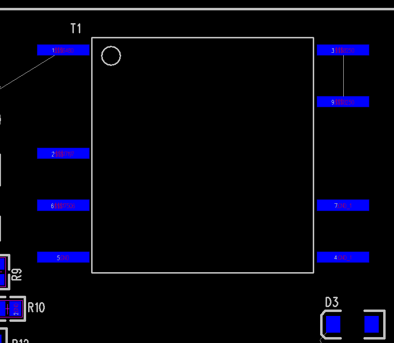
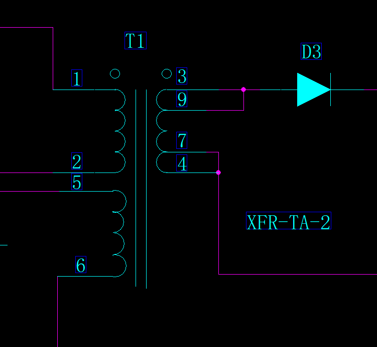
  • hello ulrich, This is the transformer package pin diagram and sch pin diagram,
  • Hello User5243669,

    Thank you for clicking on the "Resolved" button. I hope that you have found where the error is.

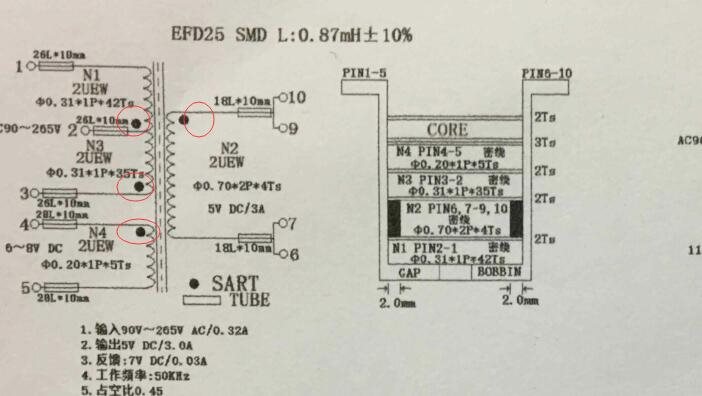
    The transformer specification schematic diagram looks normal, with primary winding 1-3, auxiliary winding 4-5, and secondary winding 6,7 - 9,10. The polarity marks in the transformer schematic are correct. The pin numbering of the physical footprint is very unusual, though.

    Normally with a top-side view, one would expect pin1 to start at top left corner (as shown), then progress down to pin 2 (the left-side missing pin), then 3, then 4, then 5 at bottom of left side. Then pin 6 at bottom of right side and progressing up pin 7, 8 (missing pin on right side), 9 and pin 10 at top-right corner.
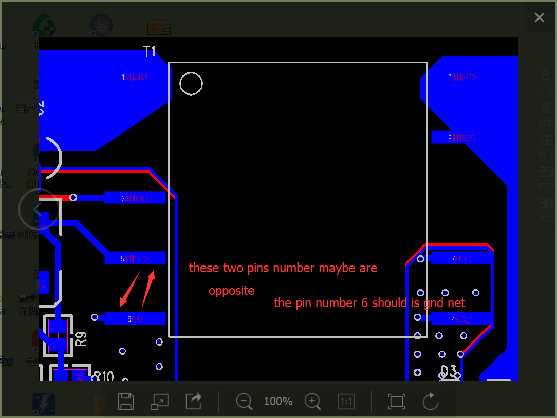
    Your top-down view has only pins 1, 7, & 9 in their expected positions and the other pin numbers inconsistent with typical numbering.

    If the transformer itself is constructed according to the specification, with the windings going to the normal pin-numbering positions, it should have worked okay in your circuit. However, if the transformer was constructed with the windings going to the assigned pin numbers, but the pin numbering followed the unusual positioning as numbered in the physical top-view, then I can see how the various component failures can happen.

    If the primary winding is wound from pin 3 to pin 1, but pin three is physically at top-right and pin 1 is physically at top-left, then there is a direct short-circuit from primary to secondary. The same with pins 6 and 7. The spec schematic has one end of the secondary tied together at 6 & 7. If the physical footprint numbering is used, this will tie the auxiliary winding to output ground.

    These connections will definitely cause component failures because the current and voltage stresses are completely different than expected from the usual interconnections.

    Please review the transformer construction thoroughly to understand how the windings are actually connected from one pin to another. The primary and auxiliary windings should all terminate on the left side (using top-view) and the secondary terminates on the right side (top view). No winding should extend from the left side to the right side. I recommend that the physical top-view pinning of the transformer should be corrected to follow the normal pin number progression, as I described above. And your circuit schematic pinning should also be corrected to follow the correct numbering (which is in the transformer specification).

    Regards,
    Ulrich

  • Hello uritch:

    the uc28700 have already work,but i find that the out voltage is ac 5v and not is DC5V. can you explain it to me?
  • Hello User5243669,

    I'm sorry, I can't explain why your output voltage is 5Vac. It is certainly not acting like a normal flyback converter.
    Can you please provide a waveform of the output voltage? Also, a waveform of the MOSFET drain voltage, if you can. (Click on the "Insert Code, Attach Files and more..." link at the lower right corner of the post box. Use the "paperclip" icon to attach waveforms and other files.)

    Have you checked your transformer construction as I recommended earlier? If the transformer connections are not right, nothing will work correctly.

    Also, please double check the orientation and values of components on your circuit board. Do not automatically assume that a prototype board is assembled correctly, even if the schematic diagram is correct. Sometimes polarized parts, such as diodes or electrolytic capacitors could be mistakenly installed backwards, and the board appears to be correct at first glance but does not function properly.

    Regards,
    Ulrich
  • Hello uritch:

                   thanks for  you patiently answer,i have already double checked  the values of compent, and i find  that there are not any compent  weld error. the transformer auxiliary winding pin number  maybe  error, 


  • Hello urich:

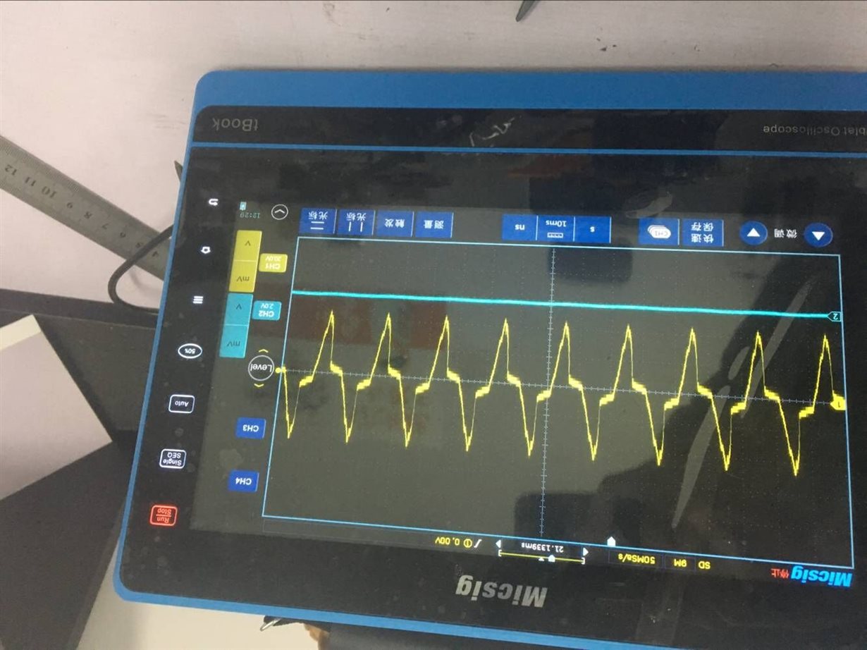
                             this photo is  the voltage  of  vout  ,i find that the voltage is AC 40V.

  • Hello uritch:

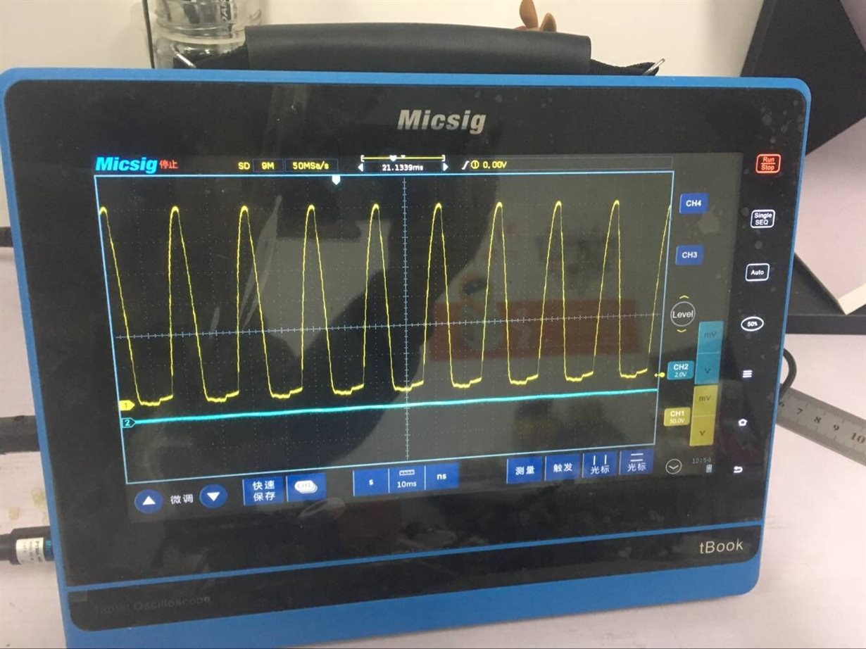
                                this  photo is the voltage of Drain

  • the Voltage is 300V
  • Hello Uritch:

    the Voltage of Drain is about 300V,it is a Pulsating dc whch we can see in the photo.
  • Hello uritch:

    why the VOUT VOLTAGE is AC 5V ? Now the problem is not be resolved ? can you give me some advises ? why the vout voltage is AC 5V ?
  • yeh ,is it normal? now the output voltage is AC and the effective value is 5V. can you give me some advices to solve it ?
  • Hello User5243669,

    I'm sorry for my delayed response. The voltage peaks that you are seeing in the last two photos posted occur at the rectified line frequency of ~100Hz (they recur every 10ms); I assume a 50Hz input line frequency. This comes from incorrect probing.
    I believe that you are measuring the output voltage and the drain voltage with your 'scope probe ground-wire connected to earth GND. Or perhaps there is a break or open-circuit in your probe ground clip or wire.

    To look at the output voltage, connect the scope probe, with its GND, across the output capacitor.
    To look at the primary-side MOSFET drain voltage, connector your probe ground to the negative terminal of C2. It is very important that your AC source to the converter input is isolated from the building AC line.
    Use a 1:1 isolation transformer or an electronic isolated ac source! A variable transformer is not good enough because it does not isolate primary to secondary.

    The reason that isolation is necessary is to avoid damage to your circuit or to your oscilloscope. The 'scope and probe GND is directly connected to earth-GND through its line cord. If you connect the probe GND to the C2 negative and the converter AC source is not isolated, there can be a very large current surge from the AC line through the bridge diodes back to earth-GND by way of the probe ground. At best, this will only blow the board fuse. At worst, it can also destroy the diode bridge and possibly damage the oscilloscope.

    Regards,
    Ulrich
  • Hi ulrich:

                       mabe be you make a mistake.  the input is ac 220v  50hz   in china ,so the 50hz  is normal.  the  measure datas are the same throuch the method you said.

    \


  • hello  ulrich:

                         i am forget to  tell you  that  the compement   D3  C5  and  C6  are not  welding , is it the reason that out the ac voltage?    i  measure the  OUT AC  voltage   efffective value is  5v.  

  • HI ulrich:

                        why not anybody  answer my question ?   is there a  expert  help me to solve  this problem?   


  • your employees are so irresponsible. this has been a problem for two weeks , the ulrich has not been solved ,and not answer my question any more ? this is how you work?
  • user5243669,

    I'm sorry to hear you have concerns with the support you have been receiving from one of our product experts. I am an Applications Engineering manager here at TI. I admit that some of the response times have been slow and we can improve there going forward. We appreciate your interest in TI and will work with you to be successful in your design.

    To move more quickly, would you be more comfortable communicating with TI in Chinese? We have a Chinese language version of E2E here:

    https://e2echina.ti.com/

    If you send me the link to where you post your question, I will assign an applications engineer fluent in Mandarin who is also a UCC28700 product expert to support you. please email me the link of your e2eChina post to john.stevens@ti.com and I will assign such support.

    When you post on e2eChina, I encourage you to provide full information on what your input voltage minimum and maximum are, what your output voltage is, and what your maximum output current is. You may consider to fill out the UCC28700 excel design calculator and attaching that to the post to show clearly specs of your design and how you chose the components and transformer specs. That design calculator can be found here:

    www.ti.com/.../toolssoftware

    If you are doing common outputs like 5V, 12V, etc. we also have many reference designs online that you could compare or copy for your own design. By using this website below you can select AC input, isolated, and select your output voltage in the pane on the left and you will see multiple reference designs come up, some using UCC28700, some using other controllers.

    www.ti.com/.../reference-designs.html

    With your design specification of Vin/Vout/Iout we could also help you find a good reference design to compare to. sometimes it's fastest if we already have a design to build boards using that design you can avoid risk and debug of starting a new design.

    Let me know if you have any questions.

    Regards,
    John