This thread has been locked.

If you have a related question, please click the "Ask a related question" button in the top right corner. The newly created question will be automatically linked to this question.

UCC28180: UCC28180 can not over current protect?

Part Number: UCC28180
Other Parts Discussed in Thread: PMP20612, LM8364

Can anyone tell me if the addition of the diode across the inductor and boost diode would take care of the issue of no overcurrent protection?

I am experiencing the same issue that when I turn off the AC input, and turn it back on again, the current sense resistors incinerate and mosfet shorts.

If I wait for high voltage to drain off, then circuit powers up fine.

In reference to the datasheet for the UCC228180 (SLUSBQ5D-NOV 2013), Figure 29 shows the diode D2 as part of the reference design.

What is the function of this diode?

Any information would be greatly appreciated.

  • Hi John,

    Thanks for your interest in UCC28180. This is a bypass diode. Its main function is to bypass the current around the inductor and boost diode during startup. The reason this is done is in a boost configuration the inrush current is not controlled by the converter because the input voltage is still greater than the output voltage. The diode bypasses the large inrush current around the inductor and boost diode.

    When AC input is only briefly removed, does the converter continue to switch? When the AC line browns out the peak current in the inductor and mosfet becomes quite large. You can add an external brownout circuit to pull VCOMP low when the AC line is removed. For reference, take a look at PMP20612. An external brownout circuit was added using LM8364:www.ti.com/.../tidrqy2.pdf.

    Best Regards,
    Ben Lough

  • Hi John Malnar,
    Thank you for your interest in this part.
    Diode D2 provides a path for the in-rush or charging current flowing from the Line to C16. It diverts much of this current away from the boost inductor (L2) and diode (D3). The part used here can be a slow diode that handles the in-rush current more easily than the fast boost diode.
    I suspect that your issue with the short power-OFF is that the VCOMP network remains charged, and when the Line is restored it starts up with a duty cycle that is too large for the applied Line voltage.
    When you turns OFF for a longer period the VCOMP pin voltage will have time to discharge so it starts with a low duty cycle.
    I will check into this problem and get back to you if I find a suggested solution.
    Thanks
    Joe Leisten
  • Hi John Malnar,

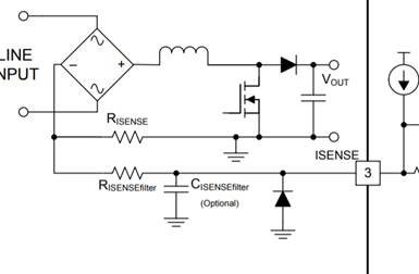
    The system designer for this part asked me to check if you have a diode from HV- (GND symbol) to the ISENSE pin as shown below.

    Thanks Joe Leisten

  • Missing diagram below

  • Hi John,

    Were you able to make any progress on this issue?

    Best Regards,
    Ben Lough
  • Hi John,

    It's been ~2 weeks since your last response so I will go ahead and close this thread for now. If you need further assistance on this issue please feel free to make a new post.

    Best Regards,
    Ben Lough