This thread has been locked.

If you have a related question, please click the "Ask a related question" button in the top right corner. The newly created question will be automatically linked to this question.

TPS65131-Q1 Overshoot issue during power up

Other Parts Discussed in Thread: TPS65131-Q1

Hi team,

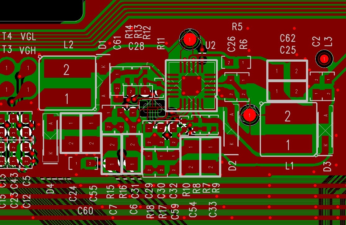
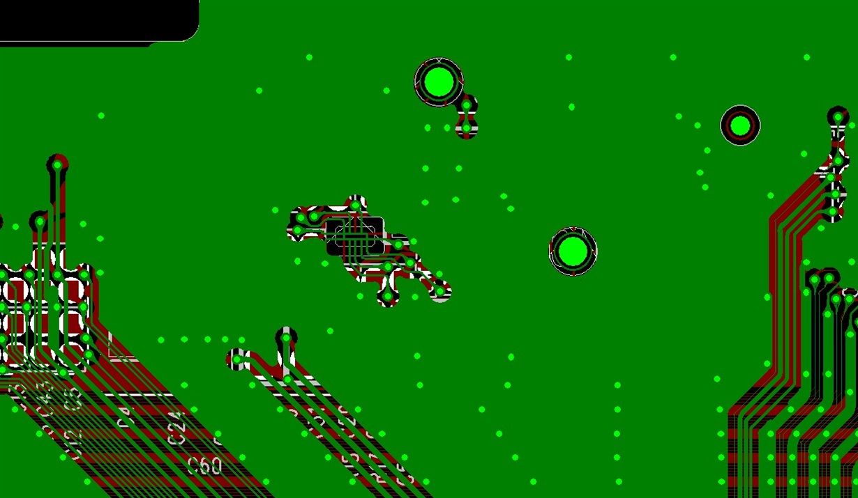
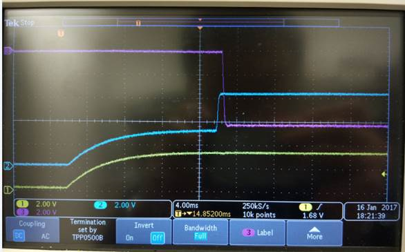
my customer is using TPS65131-Q1 in a automotive panel, during the test, they found that both Vpos and Vneg have large overshoot (hundreds of millivolt), below is the schematic, layout, bom, capture, would you please have a look and show your suggestion? thank.

dcdc-tps65131q.pdf

Toplayer

BOM 
 15pF/50V: CC0603JRNPO9BN150 ,Yageo
 10nF/25V: 06033C103KAT2A ,AVX
 4.7nF/50V: CC0603KRX7R9BB472 ,Yageo
 0.22uF/25V: CC0603KRX7R7BB224 ,Yageo
 1uF/25V: GRM188R71E105KA12D , Murata
 4.7uF/16V:GRM21BR71C475KA73L, Murata
 10uH Inductor:CDRH4D22HPNP-100MC,Sumida
Diode:1N5819HW-7-F ,DIODES

Kevin

  • Hello Kevin,

    Could you please try to set R6 with 50 Ohm or 100 Ohm. Hereby you will set a delay for VIN which will give the regulation loop enough time to regulate the output voltages properly.

    Let me know your feedback.
    Thank you
    Best Regards.
    Ilona
  • Hello Kevin,

    Additionally I don't think that the overshoot is related to the layout as the overshoot is quite slow ~ 200 us (kHz area).
    Layout concerns are related to very high frequencies > 200 MHz.

    Best Regards.
    Ilona
  • Hello Kevin,

    Do you have any feedback on this?

    Thank you.
    Best Regards.
    Ilona
  • Hi Ilona,

     Increasing R6 to 50 or 100 ohm didn't work, we also try to delay the ENP and ENN singal by changing R5 to 10k and add a 4.7uF cap to GND, also didn't work. 

    We found that by adding 150pF capacitors in parallel with feedforward cap C32 and C28 in the feedback divider, we could control the over shoot at both Vpos and Vneg (capture as below), but then this cap is 10 times large than the calculated result from Equation 11 and 12 in the datasheet. Will this cause any stability issue?

    Do you have any other suggestions to help with over shoot issue? thanks for your help.

    Ch1: Vin; Ch2: Vpos, Ch3: Vneg


  • Hi Ilona,

    Any suggestion? Thanks.

    Kevin

  • Hello Kevin,

    The feedforward network adds a zero and a pole to the control loop which in the end should lift up the margin and the bandwidth. The given formulas in the datasheet do basically describe that the zero of the feedforward-network (1/( 2*Pi*R1*CFF)) shall be in the same range as the bandwidth of the power stage (1/(2*Pi*sqrt(LC)). In general larger values of Cff improve the bandwidth however this is limited.

    The easiest and best way to check the stability is to do load transient measurement. Have you checked this?

    I did some tests in the lab and it showed that with a 10x bigger feedforward capacitance both converter still work fine.

    This application note gives you good background details about the feedforward network.


    Best Regards.

    Ilona