This thread has been locked.

If you have a related question, please click the "Ask a related question" button in the top right corner. The newly created question will be automatically linked to this question.

Power Control TFT/LCD Display (Gate Driver / Source Driver)

Other Parts Discussed in Thread: TPS65142, TPS61169, TPS65124, TPS65100, TPS65121

Hello!

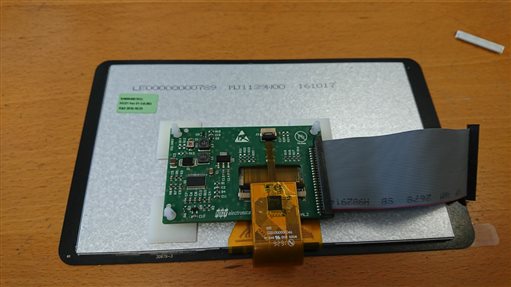
We are planning to use the TFT screens from PowerTip (PH800480T013-IBC / PH800480T013-IHC01). datasheet link: 

SPF-PH800480T024-IHC01_001.pdf

While we are developing an PCB, we found that the screen requires a power controller (it's not included in the screen itself). As shown in its Data sheet figure "2.3.3 Power On/Off Characteristics", a power sequence in time has to be respected and driven by an external power controller.

Usually, customer use LCD module with an integrated power controller, their design has just to provide a some power voltage for the LCD (can be different ones) and for the backlight-LEDs.

As far as we have seen we need these voltages to work with:

Vled+ (Voltage led): 9.9V ~ 10V 
DVDD (Digital power supply): 3.3V
AVDD (Analog power supply): 10.4V
VGH (Voltage Gate High): 16
VGL (Voltage Gate Low): -7V
VCOM: 3.8V


Our question about this is any information / support on this side. How can we manage the power easily?

Klaas de Boer | Embedded System Engineer

  • Hello Klaas,

    Below figure shows where TI can help you with getting the right content together for your display. You see that we do not provide all the what it needs for the controller board such as the timing controller, the source and the gate drivers. This has come from the panel vendor. In the panel specification on page 11 you will have the models for the gate and source driver.

    However when it comes to the green areas we can help you! In the first step I would like to ask you to have a look on the Display Power Selection Tool. This tool will lead you through the portfolio for LCD supply solutions that provides you with LCD Bias, Levelshifters, vcom and gamma buffers and led backlight drivers.

    If you have more questions on any of the parts, let me know.

    Best Regards.

    Ilona

  • Hello Klaas,

    TPS65142 might be a good starting point for checking the devices we have.

    Best regards,
    Brigitte
  • Hello Klaas,

    Do you have any feedback for us?

    Best Regards.
    Ilona
  • Thanks for your feedback!

    I have been busy with it for a while now, have been exploring different kind of chips / datasheets.

    Regarding to the Backlight Driver, is it possible to supply this directly with, lets say... 10V? Without making use of any driver?
    I do have only 1 channel, regarding to the datasheet (SPF-PH800480T024-IHC01_001)

    Some options I have seen is making a combination between the TPS65124 and TPS61169

    This actually is similar to the TPS65142 now I look at it.


    The WLED output is 40VDC / 1,5A, this is adjustable... this can be done by using an PWM signal. Are there any other options? Potentiometer?

    Are there any reference designs available? (Altium files? Or something else?).
    Is there an QFP / TSSOP / other package available?

    I just did some research:

    Another option is the TPS65100 combined with TPS61169? In this case the packages are TSSOP and SC-70. 

    Is this an good idea?


    Those are so far my questions.

    Best regards.

    Klaas

  • Hello Klaas,

    Thanks for the update. In the table below I have summarized and pointed out the main differences between the three solutions. I exchanged the TPS6124 with the TPS65121 as this integrates an LDO to supply the digital rail.

    I would recommend to go with the (3) solution as this will save you the additional vcom-buffer that you need in the other solutions. Do you have any place constraints?

    (1) TPS65121+TPS61169

    (2) TPS65142

    (3) TPS65100 + TPS61169

    External WLED Driver Solution

    Integrated WLED Driver

    External WLED Driver

    No VCOM Buffer

    VCOM Buffer

    VCOM Buffer

    Auxiliary Rail for VIH/VIL

    No Aux. Rail

    Auxiliary Rail for VIH/VIL

    Regulated VGH

    Regulated Charge Pumps

    Regulated Charge Pump

    --

    Not capable to supply 210 mA output current (max. 150 mA)

    --

    QFN + SC70

    WQFN

    QFN + SC70

    EVM available

    Request EVM

    EVM available


    To your question about the output voltage of the LED driver, I have notified the LED driver team, they are the expert for this part.

    Best Regards.

    Ilona

  • Hi Klass,

    The TPS61169 can provide the power you need for the backlight. This device has PWM input for dimming the backlight. Let me know if you need anything else.

    Best regards,
    Randy
  • Thanks for uploading a table with  the possible solutions.

    Well, I do not have place constraints yet. I cannot imagine that this part is taking a lot of space though.

    So far we have seen is solution (3) our main goal. We will develop our PCB.
    When the times comes I will give an update in here?

    Is there any component list available or Altium Library? I see that there is used some schottky diode's, but there aren't any values. Although, the datasheets does say some specification on how to choose an Schottky.
    And Altium library? I can convert the IC's itself to Altium. But I assume that there is a reference design available? This would make it a lot easier to develop.

    Best Regards,

    Klaas

  • Hi Klaas,

    Sure you can send me the schematic and I can check it. However I think if you stick with the recommendation of the EVM you should'nt need my help.

    Unfortunately the EVM has not been developed with Altium, I can only share the gerber-files with you as well as the BOM, see attached. You can convert the IC to Altium if required.hpa030a_bom.xlsHPA030A_gerbers.ZIP

    If you have problems with the design, let me know.

    Thank you.

    Best Regards.

    ilona

  • Hello!

    This is an update regarding to developing our TFT Powercontroller.

    We have been busy with testing and we came to the following results:


    First, this is our design:

    TFT Power Controller:


    And the TFT Backlight Controller:

    Voltages checked:

    VDD INPUT: 5V (+5V_IND)
    AVDD: 10.48V
    VCOM: 3.83
    DVDD: 3.3V
    VGL: -6.9V
    VGH: 20.8V (it has to be 16V??)

    Calculations made for VGH:

    1.214*(1+680K/56K) = 16V

    Why do we have 20.8V?
    Did we do the calculation wrong?

    --- Update (2017-3-13 ; 15:05)

    We soldered a 0R resistor at R6, our problem has been solved.
    We misunderstood the Doubler / Tripler effect.

    About the backlight Controller:

    Is it possible to control it with just a simple 0-5V Voltage? Or does it really need to be controlled by PWM?

    Output measured is arround 5V?

    Looking forward to some answers!

    Klaas

  • Hi Klaas,

    The TPS61169 backlight controller can be used as on/off by setting PWM input = 5V/GND, otherwise you need PWM to controll backlight dimming.

    Let me know if you need anything else in regard to the TPS61169.

    thanks,
    Randy
  • Hello Klaas,

    Your VGH converter is set as a voltage tripler because C7 is populated. In tripler mode, the IC is not able to regulate to a lower voltage than roughtly 2*AVDD. This is why you are getting 20.8V on VGH.

    Please remove C7 and populate R6, then VGH is able to regulate to 16V with AVDD being at 10.4V.

    Please have a look on page 22 of the datasheet for more details for doubler and tripler configuration.

    Best regards,
    Brigite

  • Thanks for the information!

    The display is up and running!

    Thanks for all your help / information so far.

    Now it's time for our duration test etc.

    When I need help again I will come back at you :-)

    Best regards,

    Klaas