This thread has been locked.

If you have a related question, please click the "Ask a related question" button in the top right corner. The newly created question will be automatically linked to this question.

TLC59731 doesn't light LEDs

Other Parts Discussed in Thread: TLC59731, TLC5973, TLC5940

Hi,

I am attempting to use a TLC59731 to light up a string of RGB LEDs, but am unable to make any of them light. There are 4 LEDs in the string, with an LED voltage of 19V. Forward voltages are as follows:

  • Red: min 1.7V, max 2.3V
  • Green: min 2.7V, max 3.7V
  • Blue: min 2.7V, max 3.5V

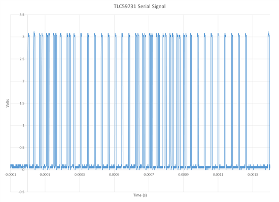
There are 220ohm resistors in series with each string. I'm using a 3.3V supply connected to Vcc, with a 0.1uF decoupling cap. The serial input is being driven by a Cortex-M4 microprocessor. I've attached an excel document of the waveform, and included a picture of it below. I have triple checked it against the datasheet, and I believe it's being driven properly. Do you have any thoughts on what may be going wrong? I can also supply other captures, if it would help.

Thanks,

Gregg

LED Driver bit pattern.xlsx
  • Anyone? Any thoughts on what might be wrong?

  • Hi Greggory, I kinda have the same problem. I'm using TLC5973 which is 12bit instead 8bit per channel, and the wave is clean as yours, but no ouput. If you find the problem, please let me know.

    Here is the post.

    http://e2e.ti.com/support/power_management/led_driver/f/192/t/365673.aspx

  • I wish you luck. I only needed to control 7 channels, so I decided to just drive MOSFETs directly from the microprocessor. I received precisely no response to my inquiries (this post and several phone calls), and was unable to get the device to work. As far as I can tell, the part does not actually function at all.

    In the end, for me, the MOSFET solution is cheaper, allows me to sink constant current through the LEDs, and actually works.

  • Hi Greggory,

    Yes,  I also took into consideration making my own constant current sink, but I have to drive 3 RGB LEDs, which means 9 channels. So, it may be cheaper, but I need to plant a lot of components. In addition to that, the uC is not actually next to LEDs, so I need to use lots of wires. The TLC5973(1) was the perfect solution, but, unfortunately seems not to work.

    There is another Chinese chip, WS2811 (and some variants) that technically does the same thing. There are even LEDs with this chip in the same package.  I've played with them, they actually work, but I have some doubts since there are coming from china...

  • At this point, I wouldn't be surprised if no one has ever gotten the TLC5973(1) working, as there are no posts on Google talking about people using them, or videos on YouTube showing them off, and TI isn't saying anything to make me think otherwise (are you going to defend yourself, TI?).

    If I was working on a personal project, I'd probably go with one of the clocked serial chips (e.g. TLC5940), or something from the series the WS2811 is in.

  • Hi greggory,

    Sorry for late reply.

    I found that you have a 33 bit input for each period but TLC59731 has only 32-bit register. Please change you signal to 32bit and try again.

    Any update, please let me know.

    Thanks,

    Rosley

  • Ok, did eventually manage to get this going.  It really is the datasheet at fault here.  Perhaps the most ambiguous and incomplete datasheet TI has ever produced?  

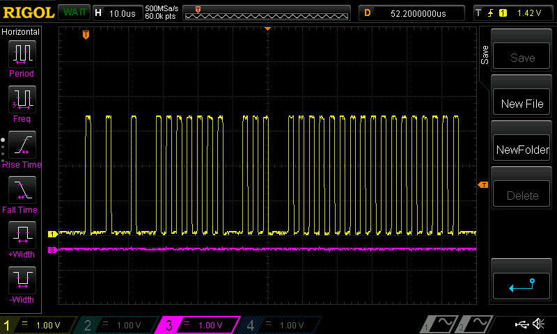
    It would appear that the Tcycle measurement sequence is the time between the first rising edge and the rising edge of the first bit.  So below here we see the 0x3A write command (b0011 1010) but with the extra measurement pulse out front.  The first PWM byte can be seen after the 0x3a command, it's 0xff in this case.

    So, it's not two pulses, it's not no pulses as I first thought, it's one pulse!  

    I2c next time people please, i2c.