This thread has been locked.

If you have a related question, please click the "Ask a related question" button in the top right corner. The newly created question will be automatically linked to this question.

LM3429 / PWM dimming and UVLO

Guru 20090 points
Other Parts Discussed in Thread: LM3429

Hello,

Could you please let me know the operation about Dimming and UVLO function of LM3429?

(1)Gate state in PWM dimming
Could you please let me know the GATE output state when nDim is low ?

According to attached image from the User's guide, ILED waveforms are different between Figure 5 and Figure 6.
Since I think that we can control GATE output by nDim pin, I couldn't understand why we could stop the LED current by nDim pin.


(2)UVLO
nDim pin is used as PWM dimming and UVLO.
Are there any difference the LM3429 state between PWM dimming Low and UVLO?
 -Low input to nDim by PWM dimming
 -Low input to nDim by UVLO

Best Regards,
Ryuji Asaka

  • HI Asaka-san,

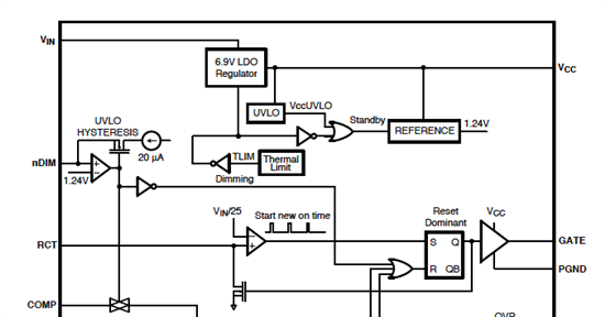
    I think the best way to think of this pin is as an enable pin. Please see block diagram below:

    According to the logic, when nDIM is low, the part is disabled and the GATE is off.  So there is no current through the LED(s) at this time. So really no difference between PWM dimming (low) and off. The current though the LED will stop when the nDIM pin is low. The reason most people prefer PWM dimming is so that the brightness of the LED can be controlled without changing the color.

    I hope this helps.

    Regards,

  • Hi,

    (1)when nDIM is low, the device will enter UVLO mode and GATE is off. For buck topology, there will be no current through LED while for boost and buck-boost topology, there will be current.

    (2)The result is same, i.e. the controller will be off and no current follows through LED(buck). You can have both features and the user guide has shown the implementation.

    Best regards,

    Victor

  • Hello Both,

    Thank you for the reply.
    I have qustion about your reply.

    (Question 1)
    I think that GATE is OFF when nDim is low due to block diagram.
    Are there other block diagram for nDim pin?

    (Question 2)
    LM3429 can be used Buck , Boost and Buck-Boost.
    And I found the schematics from datasheet P.22~23.
    Then I think that the current follows through LED when GATE is high on Buck regulator and 
    I think that the current follows through LED when GATE is low on Boost and Buck-Boost Regulator from these schematics.
    Thus, nDim logic is inverted between Buck and Buck-Boost/Boost.
    Is my understanding correct ?

    Best Regards,
    Ryuji Asaka
  • Hello Both,

    Sorry for bothering you.
    I got the LM3429 buck-boost EVM and measured waveform.
    As a result, Gate is low when nDim is Low.
    Thus I understood that LM3429 block diagram is correct.
    Then, I got additional questions.

    (1) meaning of active low nDim pin
    In the datasheet P.18, there are the description of "The active low nDIM pin".
    I think that the device is active when nDIM is high.
    Is this description incorrect?

    (2) t pulse
    I test the pulse operation of LM3429 by EVM.
    Please see the attached file as test resut.
    7345.LM3429_pulse operation.pdf

    In the attached file, ILED is 1A and tpulse is 2.75us.
    However, I couldn't control the LED current under about 15us pulse.
    And ILED is reached about 3A in spite of 1A setting.
    Is this result correct ?
    If yes, please let me know controlable minimum pulse.
    Also if there are improvement method please let me know.

    Our customer would like to use LM3429 with short pulse(2~3us) such as Flash LED.
    Thus I'm testing the short pulse operation by EVM.

    Best Regards,
    Ryuji Asaka


  • Hi,

    That might be a mistake in datasheet but nDim low will make NEFT off.

    Do you have a waveform that use real PWM signal but not a single pulse? There is normal switching in your 1st waveform. You may try to power on the board firstly and then apply an external PWM signal(you can change duty cycle but keep the off-time larger than 2.75us) to see the result.

    Best regards,

    Victor

  • Hello Victor san,

    I applied PWM signal about 200Hz and 99%~ duty in the attached data of previous my post.
    Also I applied the power on the board firstly.

    Can I use the LM3429 with my  conditions?
    I would like to confirm whether we can use the LM3429 by 2~3us tpulse.

    I didn't save the other waveform and didn't check the nDim pin voltage.
    Thus, I will check the nDim voltage for confirming the actual on-time. 

    Best Regards,
    Ryuji Asaka