I have been experiencing what seems to be a high voltage failure while attempting to drive a 58V string of leds at 1.2A (4 parallel strings of 24 LEDs which should run nominally at 58V, 300mA per string).
On my first revision, I ran 2 strings of 24 (58V @ 600mA total) with no issue. However, when I modified the current sense resistor to run at 1.2A and attached 2 more strings, the leds will turn on for a few seconds, but then the driver makes a "POP!" sound and the board dies. Also, a small chip of the corner of the driver package will occasionally break off near pins 1 and 2 during the failure. I have tried running it at both 500kHz and 1000kHz, just for kicks, but it doesn't appear to have any effect on the issue.
I put the power supply on a variac and brought the voltage up gradually, and I can get the leds to drive at about 56V @ 750-850mA, but if I take it up any further, the failure occurs. I don't have any thermal measuring equipment, but my first thought was that it could be overheating, but I am able to place a fingertip directly onto the driver and, while it gets pretty warm to the touch, it never gets hot enough to "burn" my skin. I assume that if this was a thermal issue, the chip would be way too hot to touch. Also, if I have Vin set at 60VDC, and turn it on, the chip pops immediately without ever even getting a chance to "warm up", which is part of the reason I feel this is a high voltage (arcing) issue, and not thermal.
I removed the hysteresis resistors from my design as I didn't deem them necessary, but is there something about the part that requires this? Another thing worth noting is that I used the same component values for loop compensation used in the evaluation design from the datasheet. This is my first venture into switching power supplies, and I am not very familiar with loop compensation or its theory. Could this be the reason for my failures? Is this circuitry critically necessary?
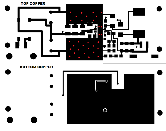
I've attached my layout below. The red dots are approximate positions of thermal vias (they weren't visible on the exported files, so I added these by hand).
Thanks in advance for any insight anyone can provide me with this problem.
-Zack K


