Hi,
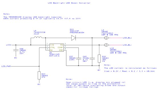
I am using the TPS61165 as a constant current boost driver for a TFT panel backlight. Part of the reason I chose this part was for the 'analog dimming' to eliminate audible noise from the inductor/caps.
I have noticed under certain combinations of input voltage and dimming level that I hear audible noise from the converter circuit.
Further investigation has led me to the cause being that the converter hits the minimum on time of 40ns and this results in a pulse-skipping mode causing 7kHz audible ripple.
The circuit input range is 10 to 15V and the output is 60mA (max) which results in an LED voltage of around 19V. We dim the LED down to 10% in our 'power save' mode.
My schematic is below:
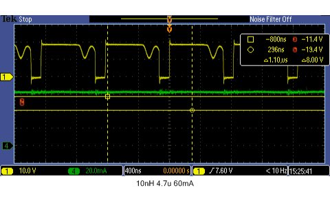
It seems with these component values the converter is barely having to switch to maintain the boost voltage and current, when dimming this requirement is less. Therefore even at 100% PWM the converter switching duty cycle is just 16% maximum. Dimming puts the converter in pulse skipping mode as the switch minimum on time is not short enough to run continuously and maintain the desired current.
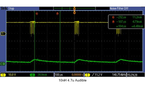
I have tried changing the inductor to 10uH (the datasheet recommends 10 or 22uH) and this improved the audible noise accross the range. At low LED PWM the pulse skipping still occurs:
(Yellow trace switch node, green trace LED current)
At 60mA the duty is only 16%:
I then tried this with a 2.2uF output capacitor but the PWM was the same and the ripple on the LED current got marginally worse.
Is it safe for me to try a lower inductance value than the recommended 10 to 22uH? I presume this is recommended for devices with larger input to output step and higher current? In my application a lower inductance would probably keep the PWM constant (no audible noise) but I am concerned about loop stability.
Mark


