This thread has been locked.

If you have a related question, please click the "Ask a related question" button in the top right corner. The newly created question will be automatically linked to this question.

LM3407 Current setting not working out

Other Parts Discussed in Thread: LM3407, TPS92511

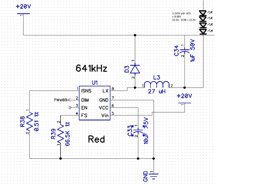
I am using an LM3407 and attempting to set the current to 350mA, however something is not working out, and I only get an average current of 247mA.

Each LED drops 2.245V@350mA, for a total of 8.98V.  The 20V supply is 22.3V.

Below are the resistor combinations that I have tried:

0.56 ohm -> 164 mA

0.51 ohm -> 171 mA

0.372 ohm -> 247 mA

I have also tried 0.56 ohm with 39uH inductor ->166 mA

Inductor: SDR0403-270KL  (27uH)

Diode:  MBR0530

Any ideas why the current isn't reaching the 350mA that it should be?

Thanks

  • HI Keith,

    My first thought was maybe you are over-heating the device. The worst case switch resistance is 1.45Ohms so with 22Vin, you may be over-heating the device. One way to test this might be to reduce the voltage by about half and see if you have similar results.

    After talking to the designer, he believes your switching frequency is too high. You may want to reduce this to see if you can get better results. He also suggested you have a look at the TPS92511 as this is a next generation device.

    I hope this helps.

  • Thanks for your response :-)

    Changing the frequency setting resistor to 130K for around 300kHz switch frequency with 39uH inductor results in 162mA.

    Changing the inductor to 150 uH with 300kHz also results in 162mA.

    The chip remains cool even after several minutes of operation.

    I measure the peak to peak current by inserting a 1.87 ohm resistor, measuring the differential voltage, and dividing by the resistance and I get 107 mA ripple.

    If I reduce the supply voltage to 12V, I get 297mA average current.  Setting the supply to 10.15V results in 350mA

    Sweeping through input voltages I get the following:

    This is a lot more dramatic a reduction than the datasheet indicates:

    Should I be reducing VIN on pin 5 to around 10V while supplying the LEDs and the top end of the Schottky diode 22.3V to cover the span of the string (and other strings)?  Can VLX be > VIN without damaging the chip?

    Thanks

  • Hi Keith,

    According to the datasheet, you should be OK with VLX>VIN, but I am checking to be sure.

    Also trying to see why your results are showing more variance than the datasheet suggests.

    Stay tuned

  • Keith:


       Can you tie the DIM pin to VCC and see if you can get the full current?


    David Zhang


    Applications Engineer

    Lighting Power Products

    Texas Instruments

  • Tying the DIM or the DIM and EN to VCC doesn't result in any more current to the LEDs.

    I get the same current as in the previous tests where I was tying DIM to the 3.3V supply for my MCU.

    Thanks

  • Keith:


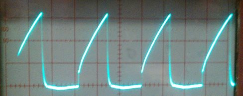
       Can you take the waveform of the ISNS pin? The average voltage on this pin should be 198mV.


    David Zhang

  • I used the digital capture feature to get these images.

    At Vin=10.5V, PWM duty = 100% DIM=3.3V, 100mV, 1us per division:

    At 16V

    At 22V

    Waveform and height are the same with DIM=Vcc.

    The sloping line pivots around the 0.198V mark as Vin is increased or decreased.

  • keith:


       The waveforms look correct. When the FET is on, the average current is 0.198V/Rsense. When the FET is off, all the inductor current should go to the LED string. But the current measurements you got seems to suggest that was not the case. Can you please remove the output cap and measure the current again? Do you have a current probe to measure the LED current waveform?


    David Zhang

  • With VIN=16, ILED=0.240A (no output cap.  Previous measurements had 1uf between top of inductor and +22V)

    I get a peak-to-peak voltage differential across a 1.87 ohm resistor in series with the LEDs of 0.6Vp-p which is a whopping 320mA p-p, if I'm figuring that correctly.  Or LED current from 80 to 400mA, which seems unbelievably excessive.

  • Decreasing VIN to 10.2V, the ripple voltage goes down to 0.035V, or Ipp = 19mA

  • Keith:


       The ripple current measurements you got are right. At 22Vin, the ripple current is large. You need bigger inductor with higher inductance value to reduce the ripple current. I don't know what kind of current meter you are using.  Is it a true RMS meter?

       The output cap suppose to reduce the LED current ripple. What kind of cap are you using? It is recommended to use 1210 size ceramic cap because the ripple current is high. If you use electrolytic cap, it won't work.


    David Zhang

  • I've added a resistor to the VIN so that when powering the circuit at 22V, VIN is around 17V, and this does not significantly extend the voltage range over which the circuit delivers 350mA.  It functions similar as before that at 22V supply I'm seeing around 180mA.

    In other words, the voltage on the LX pin (not VIN) seems to introduce the issue.  As a constant current source, it should be independent of the voltage drop across the LEDs, as this is the primary purpose of an LED driver.

    What do I have to do to this circuit to make it operate so that it is not sensitive to the LED forward voltage drop or the source voltage?

    Vsupply ILED VIN Limited VCC ILED w/vin resistor
    10.15 0.351 5.3 4.6 0.367
    11 0.324 6.17 4.7 0.338
    12 0.297 7.16 4.72 0.311
    13 0.274 8.09 4.73 0.29
    14 0.255 9.06 4.73 0.27
    15 0.238 10.05 4.74 0.254
    18 0.2 13 4.74 0.216
    20 0.181 14.97 4.75 0.195
    22 0.165 16.94 4.75 0.18

    ILED is the current without the resistor inline for VIN

    VIN Limited is the voltage with a limiting resistor

    What size output capacitor and inductor do you recommend?

    I did previously try a 150uH inductor, but it didn't have any affect on the average output current, but I can solder that in again and measure the ripple.  The setup that I use for measuring the current is to have a 1.87ohm resistor in series, then I use the differential mode on my scope and two probes to get the difference waveform.

  • Keith:


       LX is the switch pin. It switches between VIN and ground. Can you take the LX pin waveform? You can stray with 22uH inductor. Please use 4.7uF 50V 1210 ceramic cap as the output cap.


    David Zhang

  • The 150uH brings it to a 0.1Vpp, or ripple of 0.1/1.87 =53mA (VIN=16V)