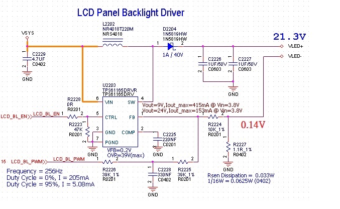
 there was a TPS61165 driving to 21V/170mA circuit as below,
and R2227 with VFB ONLY 0.14V can`t be 0.2V,and current only 130mA。
then change R2227 to 2.2R,and VFB reach to 0.2V,why ?
(we remove the PWM effect cause...)
This thread has been locked.
If you have a related question, please click the "Ask a related question" button in the top right corner. The newly created question will be automatically linked to this question.
 there was a TPS61165 driving to 21V/170mA circuit as below,
and R2227 with VFB ONLY 0.14V can`t be 0.2V,and current only 130mA。
then change R2227 to 2.2R,and VFB reach to 0.2V,why ?
(we remove the PWM effect cause...)
Hello,
What is the VIN under this condition? It looks like you are violating the Isat of the inductor. If VIN = 5V, Vout=21V, Iout=170mA, L=22uH, then the peak coil current will be ~850mA. The Isat of the NR4018T220M is 800mA. I recommend either decreasing the load condition or using an inductor with a higher Isat rating.
Thanks,
Nisha
Hi Nisha,.
the coil was changed to Isat rating to 5.4A,but VFB can`t reach to 0.2V still..
need your direction , thank you
Philip.H.,
Hi Philip,
What is the VIN of your application? You could be hitting the switch current limit of the device. You can use equations 3 and 4 on page 14 of the datasheet to calculate maximum available output current of the boost converter.
Regards,
Nisha
Hi Philip,
When the CTRL pin is constantly high, the FB voltage is regulated to 200mV typically. However, the CTRL pin allows a PWM signal to reduce this regulation voltage; therefore, it achieves LED brightness dimming.
128Hz to 256Hz PWM frequency is too low for this device, the TPS61165 only supports PWM frequencies between 5kHz to 100kHz. The requirement of minimum dimming frequency comes from the EasyScale detection delay and detection time specification in the dimming mode selection. Since the CTRL pin is logic only pin, adding an external RC filter applied to the pin does not work. Plese advise your customer to increase the PWM frequency.
Let me know if you have any additional questions.
Thanks,
Nisha