This thread has been locked.

If you have a related question, please click the "Ask a related question" button in the top right corner. The newly created question will be automatically linked to this question.

TPS92512 problem

Other Parts Discussed in Thread: TPS92512

Hi!

I use the tps92512 to build a smps for traffic light.

You can see the design cocept here: https://e2e.ti.com/support/power_management/led_driver/f/192/t/416015

After calculating the proper component values i ran the simulation and all seemed to be perfect.

But, when i tried to build a prototype all my tps92512 chips were burned...

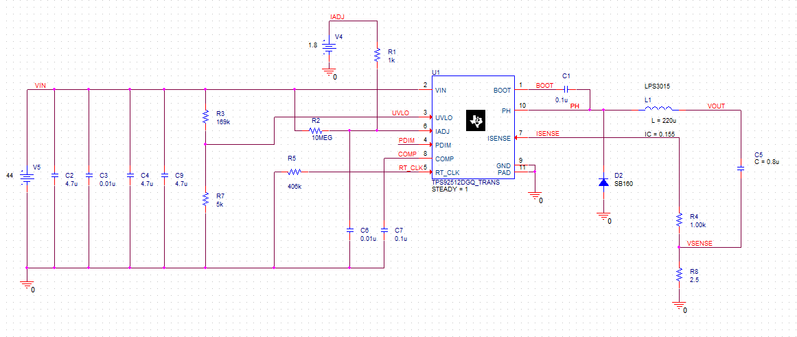
Can sb check the attached files to point me what it is going wrong???

Thank you in advance

NickTPS92512_PSPICE_TRANS.zip

  • Unfortunately I do not have the software required to look at anything in the zip file. But if you could attach a schematic with values and perhaps provide pictures of the prototype and layout I would be happy to look them over. The only things that I have ever seen that damage this IC is the input voltage exceeding abs max or a very noisy layout causing an abs max spec to be violated on one or more pins. The most likely scenario given no other information is the AC-DC converter output overshoots beyond a reasonable level.

  • Thank you Clinton for your immediate reply.

    I will attach the schematic with the values that i used to built my prototype.

    Regarding the input, I use a digital power supply, thus i can keep the voltage inside the desirable limits.

    Thank you again 

    Best regards 

    Nick

  • Sorry so slow, I was out a couple of days. The schematic looks fine. If there is no overvoltage event on the input (this should be verified with a scope shot during power up) the only thing I can think of at the moment is the layout. Do you have the capability to generate layout pics? If so I would be happy to look it over for issues. Layout is a very common issue in switching power supplies.

  • Hey Clinton,

    At this point i have run out of functional tps92512 chips so i m waiting for the new samples.

    When i eventually build the prototype again(after a week i hope...) i'll send you a photo.

    Thanks again

    You 're really helpful!

    Regards

    Nick

  • Be sure to check your board over really well before re-populating the 512s. Not only could a single component destroy the device (like if you put a diode in backwards) but whatever may have caused the damage in the first place can damage other components (again, the diode is most often the culprit, it can be destroyed by the chip failing or vice/versa).
  • Hi Clinton!

    Unfortunately i face the same problem...

    Each time the voltage exceeds 1.22V at UVLO pin the tps is burned to crisp...

    I lay me tps on a msop-10 pcb board where i connect the pin 9 with the central pad using a tiny wire.

    Then i build my protype on a regular breadboard.

    Do you think that's the problem?

    Using a breadboard on this circuit can cause problem to my tps??

    I dont know what else to think.................

    Thank you in advance

    Nick

  • I can almost guarantee that is your issue. Switching power supplies really need to have a good layout with careful component placement and good grounding. Using a breadboard makes good grounding impossible and all the extra inductances will cause some serious spiking. I suspect on the first few switching cycles the PH pin is pulled many volts below ground causing substrate injection which will damage any chip. There are some layout recommendations in the datasheet and also plenty of application notes regarding switching supply layout that should help. The switching edges are very fast in most SMPSs, a breadboard will unfortunately never work well.