This thread has been locked.

If you have a related question, please click the "Ask a related question" button in the top right corner. The newly created question will be automatically linked to this question.

TPS61195 Flashes to 100% on Initial Enable and Brightness Change.

Other Parts Discussed in Thread: TPS61195, LP8555

We're using a TPS61195 in Linear Output mode, with PWM input control (SEL1 grounded, SEL2 floating, "Analog Mode, PWM Interface").

After the board powers up, the software starts its PWM timer, sending a PWM signal into the DPWM pin, and also enables the chip by driving "EN" high.

We've previously been enabling it with a relatively high initial duty cycle, and haven't noticed any problems. Now we have a requirement to enable the driver with a very low initial brightness level, of 1% or even 0%. We're finding that with any initial PWM level of 50% or below, the device performs the slow-start, and then overshoots the target, shuts off, and then tries again. The backlight flashes (depending on PWM Phasing) at up to 100% brightness for a few milliseconds before recovering. Sometimes it takes 80ms to ramp up to the set brightness.

As a separate but related problem, with the driver enabled, but turned off (with a zero duty-cycle PWM input), changing to a non-zero duty cycle also results in a big "flash". This is especially noticeable when changing from 0% to 1%.

In the follwoing traces "EN" is the "EN" pin, "PWM" is the "DPWM" pin and "BRIGHT" is the output of a light meter measuring the backlight brightness.

Here's what happens when I enable the Driver with a PWM duty cycle of zero. It "flashes" to about 100% brightness.

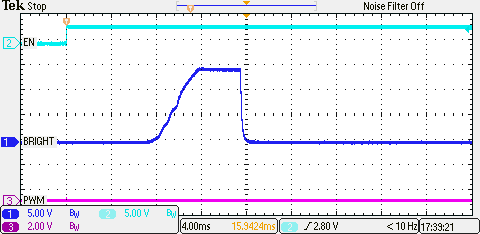
it does about the same thing when it is enabled while the PWM pin is running at a duty-cycle of 2% at 200Hz (the minimum allowed):

You can see in the above it "flashes" to something near 100%, falls back to zero, and you can see it then rise to its correct value of about 2%.

If I use a higher frequency like 1kHz this problem goes away. Here's 200Hz with a duty cycle of 50% showing the "Flash":

Here's the same thing, except with 1kHz at 50% duty cycle, now without the "Flash":

Going to a higher clock speed causes other problems though. Sometimes it takes 300ms for the Driver to respond to the Enable:

The above shows 2 seconds on, 2 seconds off with a 1kHz 50% duty cycle. Half the time it comes on within 10ms, but the other half it takes 300ms.

QUESTIONS

Why does it "Flash" at low input frequencies, and is there a way to fix this? We have a single board driving multiple LED drivers, and one model has to have 220Hz to avoid a capacitor resonance.

Why does it "Flash" with zero-duty-cycle PWM input? This is a valid user-selected value in our products.

Is there a proper specification for the minimum input frequency to avoid these problems?

Edit: Something in the chip has to "know" the difference between 200Hz and 1kHz. I'm guessing this might be one of the external resistors on the chip. Here's what the first diagram in the Data Sheet suggests, and what we're using in case that is the cause of our "low frequency problems">

Pin    Data Sheet Our Value  Notes                        

FDPWM  43.2k      43.2k      Match - PWM Input Duty Cycle

FSW    523k       560k       950kHz approx

ISET   68k        47k        27.7mA

FDIM   953k       100k       2kHz value, but we're not using internal PWM mode.

It looks to me like changing the resistor on the FDPWM pin might make the chip work better at 220Hz than it does now.  Except we're using the recommended value.

I'm a bit confused by the following in the manual:

ENABLE AND SOFT STARTUP

After the device is enabled, if the PWM pin is left floating, the output voltage of TPS61195 regulates to the
minimum output voltage. Once the IC detects a voltage on the PWM pin, the TPS61195 begins to regulate the
IFB pin current, as pre-set per the ISET pin resistor, times the duty cycle of the signal on the PWM pin.

There's no definition in the Data Sheet as to what "floating" is. What voltages? What currents? What value "pull" resistors are there in the chip and to what voltage? I'm guessing a voltage between the specified Vh and Vl of 2.1V and 0.7V.

The CPU we're using to generate the PWM doesn't have an easy option to "float" the pin as it has an internal pullup. I've tried forcing the voltage to a "floating level" of about 1V, but the chip can interpret that as either "0" or "1" and doesn't take it as "floating".

I2C Specification

We're not using this, but there's no specification of the maximum I2C frequency anywhere that I can find in the Data Sheet. Maybe that's part of the SMBus spec, but it would help if it was in the manual for anyone not connecting to an existing SMBus but driving it from I2C.

So what should DPWM be driven at (or to) when SMBus mode is used? The "RECOMMENDED OPERATING CONDITIONS" lists that "Fpwm_i" is "10kHz" when in "SMBus mode". Does that mean when using SMBus Mode a separate 10kHz signal has to be fed into DPWM? That isn't documented anywhere else. Unless that for is DPST Mode, but that is well hidden

Tom

  • Hi Tom,

    Thanks for the detailed information.  I will look into this and get back to you early next week.

    Thanks and have a great weekend.

    Nisha

  • Nisha Patel said:
    I will look into this and get back to you early next week.

    Do you have any information on this yet?

    Tom


  • > get back to you early next week

    That was two weeks ago. Have you been able to get any information on this yet? We've got designs stalled on this problem.

    After previous excellent responses from TI on technical questions, and after your first response I've been telling people that TI demonstrates how customer support can be done properly (when compared to another manufacturer I won't name here). I'd like to keep doing that.


    Thanks,

    Tom

  • Hi,

    Nisha and I are not so familiar to this device as we took it over from reorg, but we had a previous case for slow startup and flashing issue.

    First slow startup case. We saw the boost of this device never ramps up or very slowly ramps up when boost output cap is too big. For Vin=5V, Vout=35v, Iled=20mA, 4 LED channels, 6.6uF was OK, but 10uF had an issue sometimes. It seems boost regulation at startup is confused with big output cap which may cause more inrush spike while PWM input is not inputted. I think this can be fixed by using less output caps or PWM input timing earlier than EN.

    For flashing issue, there were high LED current spikes during startup. We thought this is because of driver error amplifier affected by boost voltage ramping causes inaccurate regulation and parasitic of LED cable. This might be pretty common behavior of LED drviers more or less. If you look at the pictures below, changing PWM input duty from 1.5% to 0.125% fixed this issue. But I'm not sure if this matches with your case.


    For the question about SMBUS spec, I think this device doesn't support clock speed faster than 100kHz, so it didn't specify I2C mode spec. 10kHz in recommended operating conditions will be the speed of SMBUS, not PWM input speed. I also feel this is confusing, but don't know why the original author put in this way.If you need more detail answer, I will find the original designers and ask them again. Hope this helps. 

  • Thank you for your reply.

    > I think this can be fixed by using less output caps

    Our design is using:

    Input Voltage: 8.8V
    Output Voltage: 21V
    Inductor: 10uH
    Output Capacitor: 4.4uF (2 * 2.2uF
    Current: Two Strings, IFB1-4 and IFB5-8 paralleled, 27.7mA per IFB output pin.

    Our capacitor is already less than the problematic value you have listed. All components seem to be within the recommended range

    > PWM input timing earlier than EN.

    There are two problems with this.

    1 - Inputting a ZERO duty-cycle makes it flash badly. This is a legitimate input value that the chip can't handle.

    2 - Inputting a 220Hz period PWM signal makes it flash. Using 1000Hz doesn't. 220Hz is above the minimum specified frequency, but the chip doesn't work at its minimum specified frequency. So the chip isn't meeting its specification.

    So the chip need specially crafted input PWM signals that need to be a lot higher than the specified minimum frequency for it to be able to turn on without flashing. There has to be a better way that requires less special software to use this chip.

    > changing PWM input duty from 1.5% to 0.125% fixed this issue

    In your diagram you seem to be using 10us as 0.125% of the period, and 120uS as 1.5% of the period. So the period is 125Hz. This is WAY below the minimum specification of the chip, which is 200Hz. You should be testing the chip within its published specification, which starts at. I notice that "Figure 11, ANALOG DIMMING" in the Data Sheet looks to be using 100Hz as well. There's a mismatch in the document then.

    > need more detail answer, I will find the original designers and ask them again.

    In my experience these sort of problems are usually best addressed by running the emulation software of the part (that was used to design it) and finding out what is going wrong there. That can usually lead to a solution (component changes etc) faster than trying to experiment with the real hardware.

    We have managed to partially work around this problem in software. Other customers for these parts might be having similar problems, or are having these problems and haven't worked out it is this chip causing their system problems yet.

    I can provide schematic or more traces if that helps.

    Thanks,

    Tom


  • I thought I had a fix for this - changing the input PWM frequency from 220Hz to 1000Hz.

    Except that has some horrible consequences.

    The input PWM decoder is fairly obviously measuring 256 different levels of duty cycle. It has an 8-bit resulting value.

    At 1000Hz input, there are a lot of input duty cycles where the chip can't make up its mind. It changes randomly between two adjacent brightness levels. For low ones, like 5%, jumping between adjacent values is very noticeable and unacceptable. It also misses a lot of the input levels that it doesn't miss when driven at 220Hz.

    It looks like the chip doesn't have any inbuilt hysteresys.to stop this happening. It also looks like I don't have to increase the frequency very much for it to lose resolution.

    So it looks like I'll have to write special code to run it at 200Hz most of the time, but to switch it to 1000Hz whenever the brightness changes from zero to a different value, then put it back to 220Hz a little later.

    Tom

  • > changing PWM input duty from 1.5% to 0.125% fixed this issue

    The minimum specified PWM level is 0.5% or 1% depending on the frequency. So that value is outside of the specifications.

    As well, in my testing, how badly the backlight "flashes" depends critically on the PHASING between when the PWM on-cycle starts and when the Enable pin was turned on. For some phasings (of the PWM relative to the Enable) it flashes, and for others it doesn't. If you only conducted the above two tests without repeating them multiple times you may not have seen this effect. The only way to get "good phasings" all the time is to increase the frequency of the PWM signal.

    Tom
  • I've just measured the response of the chip to different input duty cycles at two different frequencies.

    The chip is all over the place. I can't really work out what it is doing and why it is doing what it is doing.

    I have a PWM controller in a CPU being clocked at 8MHz. That means that if I set it to 1KHz frequency I can control the duty cycle to 1 part in 8000.

    I have verified with an oscilloscope that I can set the duty cycle to a specific value and that it all works as expected.

    Here's the output LED brightness (measured with a photocell as measuring the current is too difficult) with the duty cycle increasing from zero.

    This is with the frequency set to 1000Hz and the duty cycle going from zero to about 10%.

    Notice that the first step is missing. This matches the Data Sheet that says that Dmin is 1%.

    Note also that the steps aren't the same size. They alternate "short and long". This is because the chip has hysteresis between each SECOND pair of input levels. I've proved this by measuring the output level versus the input Duty Cycle, and run the Duty Cycle up and down.

    Here's the raw data. I hope I can format it into a table... Too hard, I'll try the Code Formatting instead. No, that blew up too. I'll have to HAND FORMAT it in Monospace!

    Duty	Lvl	Level mV
    0	0	0
    62	2	48.5
    61	0	
    99	3	144
    86	2	
    124	4	244
    123	3	
    162	5	350
    148	4	
    187	6	462
    186	5	
    224	7	563
    211	6	
    250	8	660
    248	7	
    287	9	781
    274	8	
    312	10	886
    311	9	
    350	11	988
    336	10	
    375	12	1090
    374	11	
    412	13	1190
    399	12	
    

    The first column is the Duty Cycle in counts out of 8000. So the maximum there is about 5%. The second column is the output "step" in the current/brightness, and the third one is the photocell voltage. The Duty Cycles go up to the point where it switches to the next level, then back to the previous one to measure the hysteresis.

    A picture is worth... I pasted one in but it didn't stick. Editing and trying again:


    I couldn't be bothered drawing a nice graph with multiple lines to show the hysteresis, but you should get the picture. In the above there's 13 units (13/8000) of Hysteresis between levels 2-3, 4-5, 6-7 and so on. There's no hysteresis between levels 3-4, 5-8, 7-8 and so on.

    If I set the Duty Cycle to 249 (249/8000 = 3.11%) the chip can't make up its mind and the output alternates between levels 7 and 8.

    I thought that going to a lower frequency would fix the problem. Here's the same thing at 200Hz:

    That's different. The steps start off even, then alternate long/short then go back to even. There are also "glitches" during the sweep where it briefly switches to the next level. Here's the graph of Hysteresis at this frequency:

    Three steps without hysteresis, then five with and three without. And if I set the Duty Cycle to 401 the output does this:

    It switches every 2 seconds or so. This is VERY annoying. I was hoping it didn't do this at lower frequencies, but it does.

    The problem with no hysteresis between levels is the chip "dithers" between the levels.

    Another problem with having Hysteresis between levels is that if I select a level that happens to be within a Hysteresis band, then if I've gone "up" to that value I'll get the lower level, but if I've gone "down" I'll get the higher one

    So it isn't consistent which actual brightness level you'll get for a specific input. This could be a show-stopper.

    It looks to me like the only way to get a consistent dimming level is to use the SMBUS interface.

    Either that or fully characterise the 255 different ranges of duty cycles the chip seems to handle, and then try to make the PWM hit the middle of each one. That assumes these things are stable over temperature, frequency and production, which they're probably not.

  • Thanks for your detail updates and I'm sorry for your experience on this device. I've asked your questions and concerns to the designer and waiting for the answer now.

    For the additional findings above, it seems the main issue is the device resolution for PWM input. It's only 8bit(255 steps). If you use PWM input signal higher than 8bit resolution, there will be high chances for the device to be confused at certain border conditions of the PWM duty. Yes, this device is old and has very coarse resolution. And it seems this design doesn't have hysteresis for PWM input or hysteresis is also very coarse.

    As you mentioned, using SMBUS will be the only way to get the stable brightness to aviod this hysteresis issue.

  • > If you use PWM input signal higher than 8bit resolution, there will be high
    > chances for the device to be confused at certain border conditions of the PWM duty.

    The resolution isn't the problem. I first saw this problem with an input that only had 100 PWM duty cycle levels.

    The problem was that at least one of those one-of-100 levels exactly matched the unstable level between two of the one-of-256 levels the chip is using.

    This is a "Comb" problem. If you have two combs with teeth as slightly (or wildly) different spacing and put them against each other then the teeth will "match" at different repeating intervals. Here's two "combs", repeating at different intervals.

    |   |   |   |   |   |   |   |   |   |   |
    |    |    |    |    |    |    |    |    |

    I was only using a very high resolution (8000 steps) in order to characterise the steps that the chip is using.

    There is no input resolution that I can use that will guarantee to miss all of the ones the chip is using. If I use 256 levels they may all miss or more may match. I don't know. It is likely that the PWM has 257 steps (off, 1-255 and on) and the chip uses 256. That's almost guaranteed to be bad somewhere.

    UNLESS. Unless I fully measure ALL 256 steps and work out the equations that determine their location. Then I can use an 8000 step input signal, but only use the values that are as close as I can get to being BETWEEN the steps the chip is using.

    I can spend a week characterising this (and measuring different units and changing temperature, frequency and margin-testing various components), or you could help me a lot by getting the designers to provide a usable formula. Figures 5 and 6 in the Data Sheet look "interesting", but aren't detailed enough to code from.

    > Yes, this device is old and has very coarse resolution.

    After reading the above from you I found more complicated devices like the LP8555 with 12 bits resolution, "Hybrid Mode" and optional factory programmed internal EPROM. I see what you mean.

    > As you mentioned, using SMBUS will be the only way to get the stable
    > brightness to aviod this hysteresis issue.

    We've already finished our hardware design and don't really have time to change the hardware to connect the chips to the SMBUS. It would also complicate the software, a lot (we're using Linux and would need to find, write or adapt drivers too).

    As another complication is that we have a second design that has TWO TPS61195's on it as we need to drive 8 50mA strings. That should be fine as I2C/SMBUS allows the chips to be separately addressed as long as the chip manufacturer provides "Address Select" pins on the chip so they can have distinct addresses.

    The TPS61195 is hardwired to be at SMBus addresses 0x58 (write) and 0x59 (read). So you can't have two on the one bus, but have to run two separate buses. Unless it is OK to directly parallel them, and then only ever write to them.

    Tom