This thread has been locked.

If you have a related question, please click the "Ask a related question" button in the top right corner. The newly created question will be automatically linked to this question.

LM3429 (or any switched LED driver) for general load problems

Other Parts Discussed in Thread: LM3429, TPS92690, LM3409

Hi all,

I need to drive a LR load with constant current dimming. The first solution I thought  was a linear one, but due to power requirements a switched solution is preferred. We also need a grounded terminal load, so I used the LM3429 in SEPIC configuration according to datasheet (DESIGN #8).

This IC is a LED driver but I guess it can be also used to drive any kind of load since the operation will be the same, the only problem I found is both the operation at low currents (and therefore voltage) and the noise. I guess I can improve the noise behavior with a better layout design or by adding some filters at input and ouput but I can't improve the behavior at low currents. At voltages below 3 or 4 volts I have a very noisy output and the average current measured with oscilloscope is very difficult to control, I can see a very separated peaks at the output (I guess this behavior is produced by the low internal PWM through swithching inductors).

I also tried several compensation configurations and switching frequencies in order to improve the output internal error, I improved it a little but not enough. 

The question is if this kind of switched current sources doesn't control very well at low voltages or maybe the problem is related noise. I also tried to place a Schottky diode in series with load in order to increase Vf volts the output and this seemed not to work. Searching on the net I saw several switching current sources from many manufacturers which doesn't control below 2V in example or are not able to control properly below a certain % of output current, so, may this problem be related with the own switching technology? Do you know how to solved it or improved it?

EDIT: I forgot to say that the dimming control is analog to avoid PWM resetting which caused a worse behavior. The analog control is provided by the recommended current mirror which works very good,

Regards.

Thanks in advance, any suggestion is really appreciated,

Regards.

  • I forgot to say that the dimming control is analog to avoid PWM resetting which caused a worse behavior. The analog control is provided by the recommended current mirror which works very good,

    Regards.
  • The high side sense amplifier will be out of its common mode range with such a low output voltage. It requires a minimum voltage of 3.5V (possibly higher if there is significant noise on them) at the HSP/HSN terminals to regulate properly. The TPS92690 can do this in a Cuk configuration however. There is a reference design on the web for this. Or you may consider a buck converter depending on your input voltage range. They are more simple.
  • Thanks! I tried to find this parameter in datasheet but I couldn't. According to this minimum common mode I guess that figure 5 (analog dimming) is referred to another topology, this is not valid for SEPIC in example, isn't it? 

    Solution proposed (Cuk) is not possible since our load is an electrovalve (inductor + antiparallel diode), our requirement is to supply it with one positive wire (the second terminal of the valve is grounded  and no changes can be made at the load), so with cuk configuration we would have a negative current which won't  work, let us know if there is any other configuration to work with. I can't find the buck topology for this IC but I guess that due to this low side current sensing it won't work.

    We prefer a buck-boost topology but we may use a buck solution, do you know any IC suitable for our load operation? As mentioned above we need any kind of analog dimming.

    Thanks a lot in advance,

    Regards.

  • I see. It looks like you need high side sense then. I don't have a recommendation for a buck-boost with high side sense due to the fact that all of them will require more headroom for the current sense amplifier. However, if you can use a buck the LM3409 is high side sense so the load can be connected to ground. It is designed to be capable of shunt FET dimming so the error amplifier can go to ground and still regulate. It also has analog dimming which you require. That would be my best suggestion assuming your input voltage is high enough.

  • Thanks, it seems to be a good option. However we are still concerned with the operation at low output voltages since, in example, figure 12 shows a not completely grounded output and even using 5 leds at the output (when using analog dimming). Fet shunt dimming works when PWM dimming is choosen, so maybe it is possible not to work under low output voltages although it talks about DCM (discontinuous conduction mode) which, theoretically, provides a full range analog dimming. The only con is the loss of linearity within this region, am I right?

    Thanks a lot for all suggestions and time,

    Regards.

  • You can dim all the way down with the LM3409 but you are correct, like most regulators it will not quite dim all the way to zero and when the inductor current becomes discontinuous it will lose some linearity. It is almost impossible to achieve linearity when in DCM since all sorts of things factor in such as how much the inductor rings. But it can provide nearly full range analog dimming, and if the current ever needs to go to zero you can either pull the UVLO pin to ground (this stops switching but keeps the part alive) or you can use a load resistor in parallel with the load to make sure the minimum current at IADJ=0V will go through it instead of the load.
  • We'll try this device, it seems to be the best option up to now. The resistor solution at the output I guess it is not suitable for us, since this resistor needs to be much lower than our load, which will cause a current consumption at low voltages probably enough but it will also request higher current than load during the full range functioning.

    However this low current depends on the selected full-scale current apparantely, so reducing to a maximum 600 mA range there will be a lower enough current at the output, we'll see.

    Thanks again, we have enough for testing this IC, if you find any other possible way to decrease this zero current or to improve the linearity we really appreciate these inputs.

    Regards.
  • Hi again Clinton,

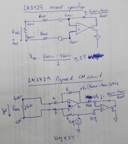
    I've been thinking about the common-mode issue and I have a possible solution that may work. Taking a look at the high-side operation I think we could increase the common-mode by using an instrumentation amplifier with an adding reference, this will simulate the LED string and, in case the real problem is the common-mode it should be fixed.

    The instrumentation amplifier would be configured to included a certain offset with a voltage reference (or even with VC output of internal LDO) the HSN pin should be tied to this reference while the output of the instrumentation amplifier should be placed in series with Rhsp (if unity gain otherwise Rhsp should be G*Rhsp), find attached a draft of the circuit. The only concern would be to find an instrumentation amplifier with a higher than supply common-mode, the operation of the full-system would be the same I think.

    Do you think this solution would work? We want to have a full-range dimming, if the only problem we have is the common-mode (no zero current dimming problem) I think this would be enough.

    Thanks!

  • That might work, I'm not sure. I don't have much bench time with this device and I've never tried anything like that. It could be worth a try, you just may need to reduce the bandwidth (larger Ccomp) if it introduces any poles or zeros that could affect the control loop.

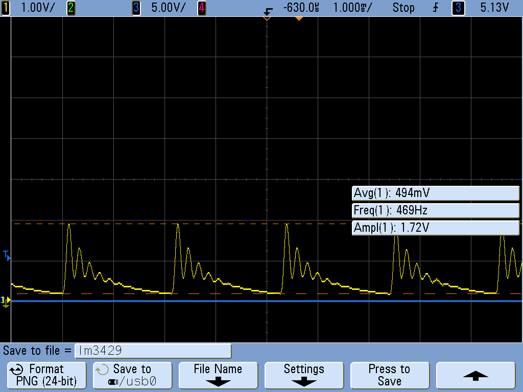
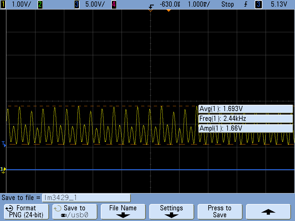
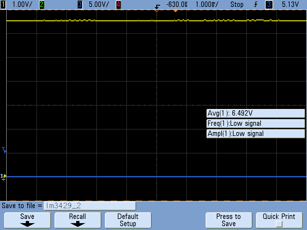
  • Hi Clinton, I've tested the proposed circuit, we have now a CM of almost 6 volts which is much above of minimum common mode needed. We still have the same behavior as before so the problem shouldn't be related with CM at these pins (at least for proposed values), it seems to be a problem concerning the control at low currents or maybe CM at the input should be much higher (as figure 5 of datasheet shown for Vo 20V) or maybe this analog dimming figure is for another topology (not SEPIC). Find attached some screenshots taken during test for different output voltages (load is a 27 Ohm resistor), this is for output voltages lower than 5 V, from this value the output signal is very stable and clean:

    Could you confirm us the full range analog dimming using this topology or for another CM? Both input and output are well filtered by two Pi filters (Without them the noise is very noticeable), PCB segregation is fine and EMI bypass caps have been placed, the IC layout is also OK.

    Regards.

  • I have not used this device in sepic configuration myself, but there are some things to consider that I do not see in design #8. First, it doesn't look like that design was specific for analog dimming. It can be done of course, but as mentioned, you may need to increase the COMP capacitor 4x to analog dim well due to the change in stability over the current range. Second, I see this design does not specify a coupled inductor. That is always the best way to go for a sepic, something like the MSD type inductors from Coilcraft. This is not absolutely necessary and two inductors are fine, but you almost always need a snubber across the sepic cap with two inductors to get rid of the ringing. You will likely need to put an RC across it with the cap 3x the value of the sepic cap and then tune the R for your application to get rid of the ringing.
    All that being said, the full range for dimming really is app specific for the most part as you will eventually run into a minimum ON time situation so the amount of energy transferred to the output will depend on component values (Ls and Cs mostly) and you also have some amplifier offset that will limit the minimum sense voltage.