This thread has been locked.

If you have a related question, please click the "Ask a related question" button in the top right corner. The newly created question will be automatically linked to this question.

TPS 92210 PWM dimming controller powering problems

Other Parts Discussed in Thread: TPS92210

Hi, I am working on a PWM based dimming method (by varying the Vref using PWM in the secondary side) for LED lights using TPS92210, I would like to add a controller setup which consumes about 5V/150mA in the Primary side of the TPS92210, because if I implement it on secondary side and Light is dimmed to 0% light level there won't be any power transfer through transformers so my controller setup cannot wake up, so I would like to implement on Primary side, I am facing few challenges to implement it, I did a small circuit and added in the schematic (inside orange lines). 

Add on circuit description:

During normal operation (other than 0% light level) the Controller part takes power from the Bias winding (Pin = 10W@40% dimming level), when it is completely dimmed that is no power transfer to bias winding the controller takes power from Source of the High Voltage Mosfet (V=13VDC) at that time Pin = 17W, 

Expected Pin = 2 to 4 W at 0% light level, please go through and help me to fix this problem

Note: 

It is observed that Pin at 0% light level (dimmed position) varies directly proportional to Vin

Pin = 17W @ Vin = 230VAC

Pin = 8W  @ Vin = 100VAC

Vin = 230VAC; Frequency = 50Hz, Switching freq 85KHz, Vout = 27VDC, Iout = 0.95A @ 100% light level

Designed for universal Input voltage

  • The power dissipation from the linear regulator, Q1, and the circuitry it is supplying for 5 volts 150 mA will be 150 mA times the average input voltage, 230/0.707*.636= 207 volts average times 150 mA or about 31 watts.  Not sure what your 5V converter is but I'm guessing it must be a buck otherwise your power measurement would be higher.

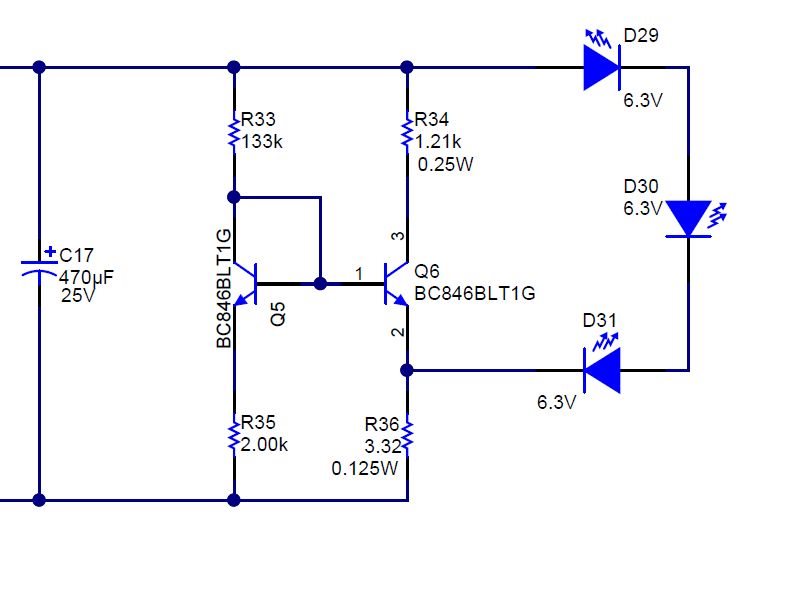
    I think what I would try to do is make the secondary side never shut off so you can place your circuitry on the secondary side or leave it on the primary side.  The way I would try to do this is to make sure there is always a small amount of current going to the LED string to keep the power supply running, basically never shut it off.  So zero command would not really be zero current.  To turn off the LEDs I would have enough loading (either resistive or active) to cause the LEDs to go out but still burn enough power in the loading circuit to keep the power supply running.  Since the IC is trying to regulate current in the LED string you could still draw a decent amount of power through the auxilary winding(s) though you have to keep the leakage coupling between the windings in mind.  Note that you may have to add a diode from the aux winding so it cannot pull current through the TPS92210 linear regulator if the bias voltage gets low enough (for primary side use).

  • Dear Irwin, Thanks for the reply, me too prefer the converter to be connected on the secondary side, if I need to do so., do you have any suggested circuit (active load circuit) that can be implemented to our project ? so that I can turn off the LEDs during 0% dimming function

  •  This is a loading circuit I've used previously.  You may need to add more loading to keep the supply running and be able to shut off the LEDs but it shows how to implement the loading.  You can simulate it and change values to get what you need.  Note that the transistor loading and the resistors will need to be able to handle the power dissipation.  This was not much loading in my case so you may need to change it to make your system work.