This thread has been locked.

If you have a related question, please click the "Ask a related question" button in the top right corner. The newly created question will be automatically linked to this question.

TPS61170 ripple issue

Other Parts Discussed in Thread: TPS61170

Greetings ESC. My customer is using the TPS61170 as a boost driver to drive an LED string for optical measurement.However, he is having a challenge with the ripple and needs suggestions. the following is the description. Please advise.

"The receiver (photodiode) has a large gain, therefore, I want the LED light to be as stable as possible so we don’t see the fluctuation at the photodiode output. I though TPS61170 will be a good choice, but I ran into the problem as follows:

Requirement:

-          Voltage input to TPS61170: 3.3V

-          Voltage output from TPS61170: 3.3V to 18V

-          PWM voltage control : 10% -90% duty cycle

-          Current requirement: 250mA

-          Adjustable drive LED voltage: 3.5V  to 18V

-          Change R1 on the eval. board to 100K

Problem

-          Get 50mv ripple at low current around 10mA at 25%duty cycle, output voltage~3.7. I can live with it

-          Increase the PWM to 35% - current output of the TPS61170 is fluctuated – from 100mA to 200mA

-          Increase more than 40%, Voltage output is swinging ~ 4V


My question:

-           Can we use this chip to drive the LED using PWM to increase the voltage from 3.3V to 18V?

-          We also want to drive the TEC ( Peltier) in the same way. 0.5V to 5V – 0.9A max

  • Hi Madhuri,

    Could you please share your schematic with us? So that we can check whether this a loop stability problem or something eles.

    One question, when use LED as load,  the output voltage is constant. Why in your applcation, the output voltage is changeing, is that because the number of the LEDs is changing during the application?

    BR, Helen

  • Hi Helen,

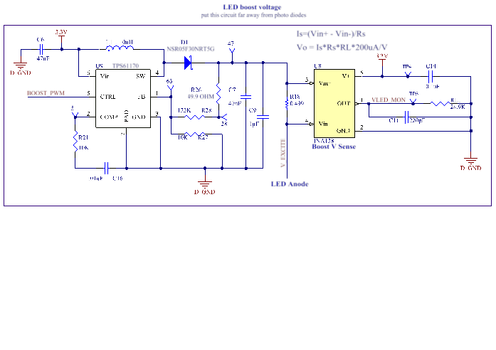
    Thanks for taking this case up. The customer is using this chip to drive Red, Blue, Green , and Purple LEDs by multiplexing them. Since each LED has different forward voltage and they want to control the current to the LED; therefore they have to control the voltage output to the LED . Voltage drop for the chain of red LED is 3.2V, voltage drop for the chain of green is 16V. Below is the drive circuit:

  • Hi Madhuri,

    Thanks for the schematic. But I can't see the parameter clearly, you can send the original schematic in pdf to me, my email address is helen-chen@ti.com

    It looks that the compensation parameter in the schematic is 10K/0.1uF, please change them to 1k/100nF to see whether it will be help.

    Three more question:

    1) The Red, Blue, Green , and Purple LEDs is paralleled together? Or they were connected to the output of TPS61170 at different time by external  switch.

    2) what 's the frequency of the PWM signal?

    3) I see a IC was connected at the output   side of TPS61170, what's the function of this IC, I can't see the name clearly.

    BR,Helen