This thread has been locked.

If you have a related question, please click the "Ask a related question" button in the top right corner. The newly created question will be automatically linked to this question.

Design LP5531 for 4 devices

Other Parts Discussed in Thread: LP55231

Hi ,

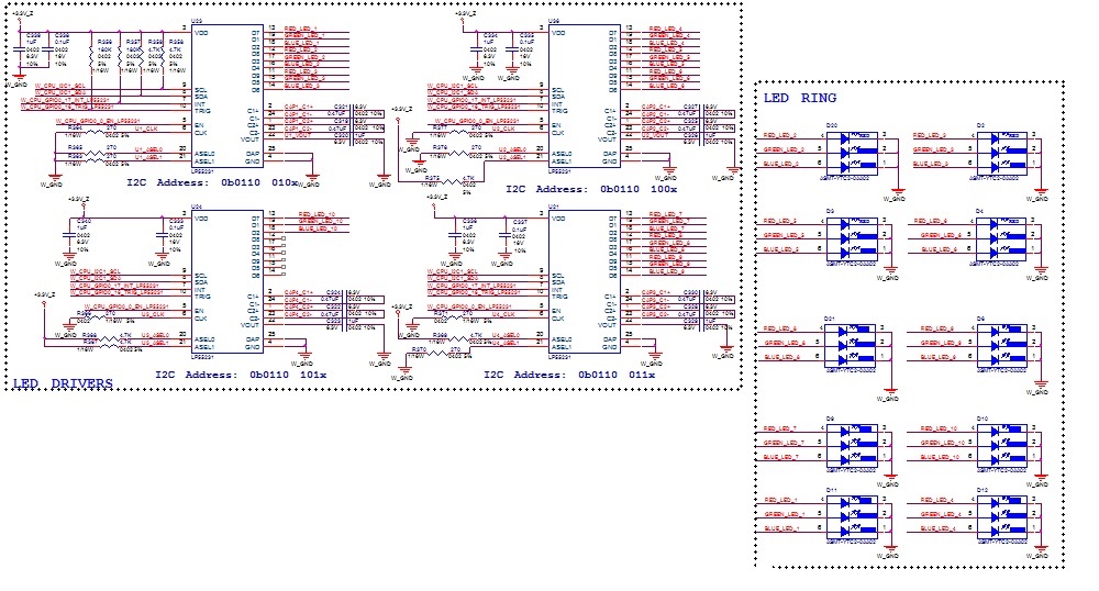
I designed and built the LED system that using  four LP5531  shown blow:

As you see, I using design led ring with LP5531 but I not sure about connection the W_CPU_GPIO0_17_INT_LP55231 and W_CPU_GPIO0_16_TRIG_LP55231 signal on pic.I also not sure  about the resistor pull up 180K. Please give me option about this design.

Thanks

  • Hi,

    I am not able to read the signal names from the picture, the resolution is too low. However, base on the signal name, I guess you are trying to connect INT and TRIG pins.

    INT pin is meant for LP55231 to send an interrupt to the micro controller, it is an open drain pin, so you can connect all INT pins together to the same GPIO pin on your micro controller. It is up to the micro controller to read back the status from all 4 devices to determine which device assert the interrupt. There is nothing to stop you from using 4 GPIO pins, one for each INT pin.

    TRIG pins are used for synchronization between LP55231 devices. They should be all connected to each other if you intend to use the TRIG instruction with ext trig. Don't forget the pull resisters since TRIG pin is also open-drain pin.

    Please refer to page 48 of the datasheet for a typical application diagram using multiple LP55231.

    Regards
    H L

  • Thanks you for your support !