This thread has been locked.

If you have a related question, please click the "Ask a related question" button in the top right corner. The newly created question will be automatically linked to this question.

TLC5940 random behavior

Other Parts Discussed in Thread: TLC5940

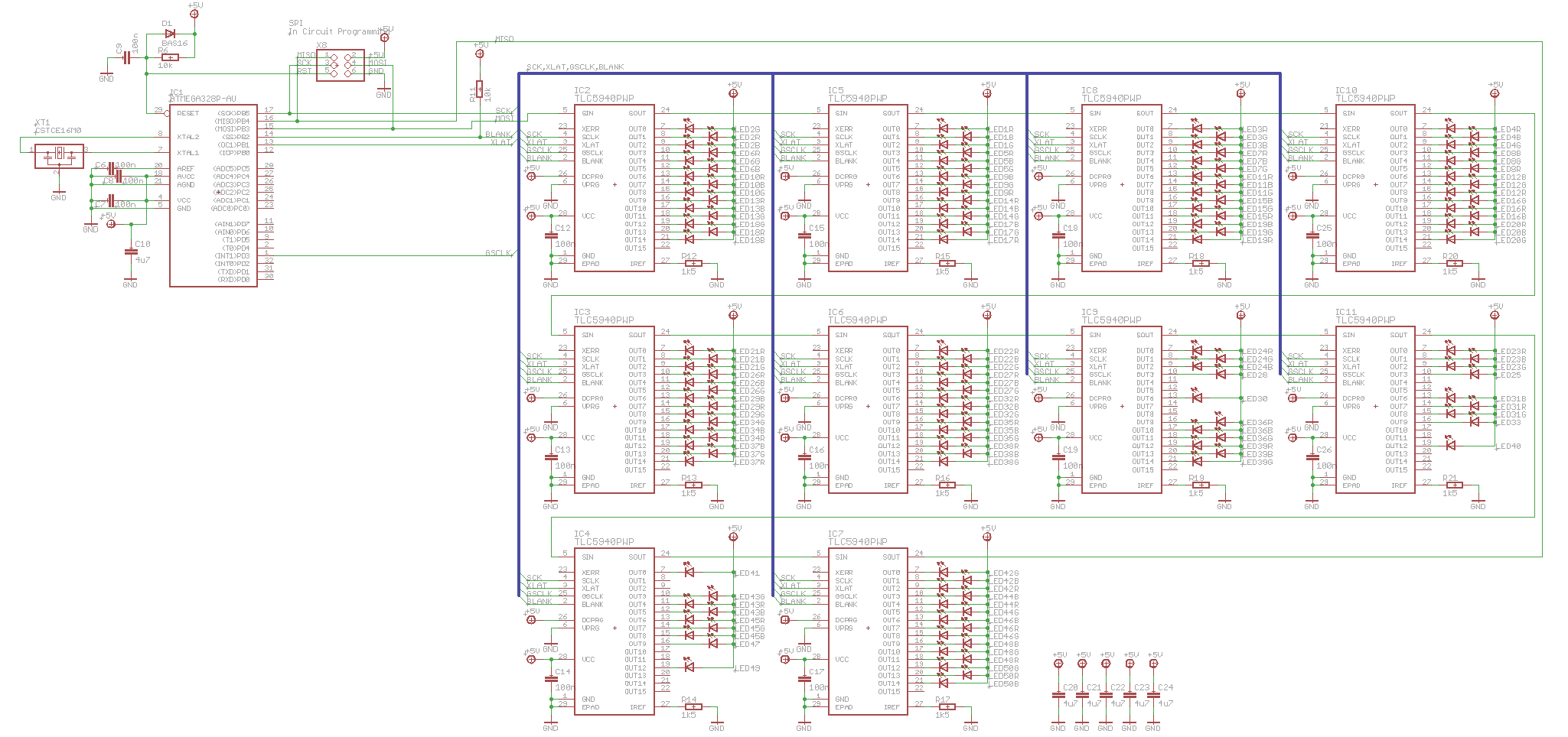
I'm using 10 pieces of the TLC5940 in a daisy chain configuration, here is my schematic:

In rare cases it happens that one ore more of the LEDs are wrongly set.

For further investigation I created an firmware, where all LEDs are controlled with the same brightness directly after power on. So if I toggle my power supply very often, I see sometimes LEDs with different brightnesses. Usually this happens in 1 out of 50 trials, but sometimes more often.

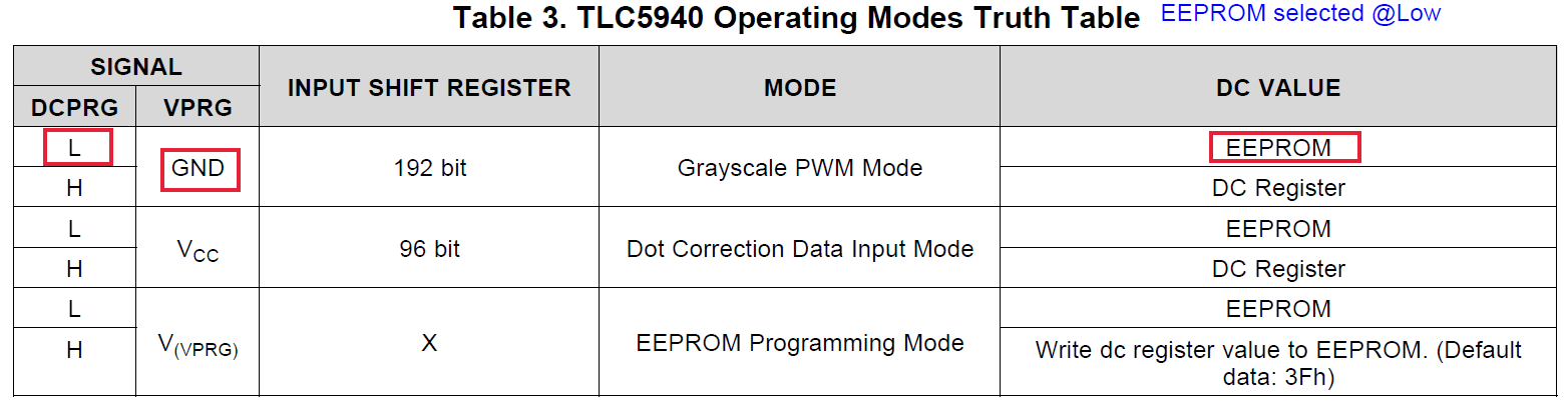
I suppose, this behavior could have to do something with the Dot Correction. I can't write Dot Correction Data directly as I don't have the I/O pins for DCPRG and VPRG in my target application (the above schematic is only a subset). But the datasheet is describing the alternative method with only one sentence:

The other solution is to overflow the input shift register with 193 bits of dummy data and latch
it while TLS540 is in GS PWM mode.

My question is, how to perform this in my Daisy Chain configuration? Normally I would shift out 192 bit x 10 = 1920 bit of Grayscale PWM values. Do I need to shift out 1930 bit or 1921 bit?

One more text in the datasheet confuses me:

The first GS data input cycle after dot correction requires an additional SCLK pulse after the XLAT signal to
complete the grayscale update cycle.

Are both sentences related to each other? And again, how this has to be done in my Daisy Chain configuration - how many bits in total?

Any ideas?

Thanks in advance!

  • Hi Andreas,


    Sorry for the late response.


    According to you described that you couldn’t write Dot Correction Data directly as you didn’t have the I/O pins for DCPRG and VPRG, so you may want to recall DC Data from EEPROM. But refer to your schematic, VPRG=0, DCPRG=+5V, the DC Data still comes from the DC Register. Table 3 shows the operating modes truth table. In this case, you could try DCPRG=0.


    Total dummy bits should be equal to 192×10+1=1921 bits.


    BRs,

    Ryan Hu

  • Hi Ryan,

    recalling data from EEPROM would require to write data first into EEPROM - right? This wouldn't help me, as it would require a programming voltage that I don't have in my circuit.

    The best option for me would be no change of hardware, so I would be happy if I can reset  the DC registers by an additional bit. Am I right, that this additional bit should be shifted out first? This also should be shown in the datasheet in Figure 18 ...

    Best Regards,

    Andreas Lindner

  • Hi Andreas,

    EEPROM has default data: 3Fh, but if you want to change the default data, you would require to rewrite the data at least one times.

    You couldn't reset the DC registers because TLC5940 will never enter the Dot Correction Data Input Mode per your schematic with VPRG=VCC...

    How about rewriting data to the EEPROM for just one times on condition that VPRG=VCC and DCPRG=0? I mean try to let TLC5940 enter the Dot Correction Data Input Mode by changing the signals DCPRG and VPRG temporarily, once rewrited, restore the conditions.

    BRs,
    Ryan Hu
  • And just as a suggestion, the unused pins should be disabled by setting DC value or GS data to "0" for a better performance....
  • Hi Ryan,
    I don't need to change the default DC data. I just want to make sure that some default Dot Correction Data is always used by the chip. And any hardware change is difficult because it requires to lift up pins of these tiny TSSOP housings from the board and rewire with tiny wires.

    Btw., do you have any idea how it can happen that all LEDs have different brightness's after power up and writing the same PWM values? I realized this can be forced by some type of power supply, while it rarely happens with other type of power supplys? We also found, that additional capacitors on power supply improved the behavior a little bit.

    For unused pins I already set GS = 0.

    Best Regards,
    Andreas Lindner
  • Andreas,

    You wanna use the default DC data from EEPROM, but DCPRG = +5V, that menas the DC data comes from DC Register, moreover the values in DC register is unknown just after power on and new DC data never writed to the DC register. So could you please do some test with DCPRG=0V?

    BRs,
    Ryan
  • Hi Ryan,

    I modified one PCB and it seems to work very well so far - all LEDs have the same brightness now.

    However, I'm still interested, why it was not working first when I tried the additional clock pulse?

    Thanks again for your help!

  • Hi Andreas,

    Congratulations to your achievements! Could you please share the changes with me, the changing of DCPRG or VPRG? It will be helpful for our further discussion, thanks!

    BRs,
    Ryan
  • Hi Ryan,
    I did as you recommended and connected the DCPRG pins to GND.

    Kind Regards,
    Andreas
  • Hi Andreas,

    Ok, if so, the root cause is obvious. please refer to Table 3 on page 18 in the dataheet. VPRG=GND & DCPRG=Low, making the DC value selected from EEPROM. 

    Thanks for your business time, is there any discusion you wanna talk with me, I'll be just over here...

    BRs,

    Ryan

  • Yup, that's clear now.
    But again, why it was not working first when I tried the additional clock pulse? Any ideas?
  • Hi Andreas,

    You mean your previous timing could not work on condition that VPRG=GND, VPRG=+5V?

    If so, in other words, the Dot Correction data is random and out of your control, couldn't be writen by your current configure.

    Ryan
  • Hi Ryan,

    I mean, Dot Correction data is random if DCPRG=5V and VPRG=GND. It's not possible to reset DC data by sending an additional clock cycle.

    Best Regards,

    Andreas