This thread has been locked.

If you have a related question, please click the "Ask a related question" button in the top right corner. The newly created question will be automatically linked to this question.

TPS61180: TPS61180 operation using resistor test loads

Part Number: TPS61180

Hello,
Has anyone had any experience using resistor test loads on the TPS61180? Using resistors, we found the Fault protection PFET will not properly turn on. With the Fault PFET bypassed, resistor test loads perform fine. We've found a possible workaround to allow the Fault PFET to turn on, and would like to understand if our solution will be reliable in production test environment.

The LED loads in our product application have seen no issues with the Fault PFET turning on, which uses 7 series LEDs in each string, resulting in a Vout (Anode) level of about 22V. ISET = 57k for 21.6mA.  System Vbat = 7.4V nominal.

For the 1.33k resistor loads in our test fixtures, with the Fault PFET bypassed, Vout properly rises to 29V. But with the PFET in line, it fails to turn on using various resistor loads (such as 1.0k resulting in 22V), and various IFB combinations by disconnecting/disabling outputs with 10k resistors to ground. Varying the sequencing of the EN and DCTRL (PWM) pins also does not help. Bypassing the PFET always allows the various resistor and IFB combinations to perform as expected.

Our workaround solution, we discovered, is to first enable the TPS61180 for several milliseconds, long enough to allow the internal soft start resistor to charge the Vout cap to about 5V (Vbat - 2V). Then release the enable for several milliseconds and then re-enable. The Fault PFET then properly starts every time on the second enable. If we wait too long (several seconds) before disabling & re-enabling the second time, the Vout cap will discharge below 1.0V, and the Fault PFET will again not start. Vout must be above 1V to allow the second re-enable to work.

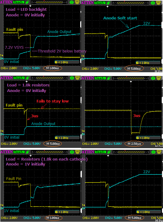
The 1st row of waveforms below show Vout (Anode) and the Fault signal with LED loads. The 2nd row of waveforms use resistor loads with Vout initially at 0V resulting in the Fault output only remaining active for 3us. The 3rd row has Vout initially at 1V resulting in similar waveforms as the LED load.

We are fine using this workaround procedure for our production tests, as we can re-enable well before the output cap discharges much at all, remaining well above 1V. But without understanding the fault circuit operation and thresholds, we have concern if this workaround is reliable. Could we have false test failures over many thousands of boards? The datasheet does not provide enough circuit detail to understand the fault thresholds and timing.

We prefer resistor loads over LEDs in our production test environment for better measurement stability and correlation across several test fixtures.

Thank you very much.
Norbert

  • Hello Norbert.
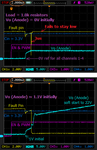
    Can you provide us waveforms with additional input Cin, EN and PWM? Our design engineer recommend you to make sure the Vo is charged to high enough before toggling the EN pin.
    Thanks.
  • Hi Daniel,

    Thank you for your comments.   Below are a couple more waveforms adding Cin, EN, and DCTRL (PWM).    In these captures, I've connected DCTRL (PWM) to EN, allowing both to rise simultaneously.  We found sequencing PWM before or after EN did not affect the Fault PFET.   Our product design has Cin connected to our 3.3V power rail which is always present when our product is powered on.  The CH4 waveform simply shows the Cin voltage level on top of our 100nF 0201 cap adjacent to pin 6.

    We were hoping the design engineer's comment could help us better understand the fault triggering with resistor loads, and why our workaround test method of enabling a second time with Vo charged above 1V allows the Fault PFET to properly remain on.  Our test sequence plan is to set enable high for 18-20ms (ensuring Vo charges to Vbat minus 2V = 5V), then set enable low for 18-20ms, and then set enable back high before the charge on Vo decays much (remaining above 4.5V).    Are we exploiting any critical timing or voltage threshold in the fault circuit which seems to be working fine for us now, but may fail on future component process lot variations?

    Thank you very much for your help.

    Norbert

  • Hi,

    I believe there is a blanking time window during startup to avoid power line FET turning off, the only difference I can think about between resistor vs. LED is the initial Vout ramping rate, did you measure the Vo, FAult signal with LED string?

    -Sheng

  • Hi Sheng,
    Thank you for your comments. Please refer to my first message which includes 6 waveforms.

    The first row of 2 waveforms use a LED load, showing Vout (Anode Output) and the Fault pin. The LED load is 7 series LEDs in each string, resulting in a Vout (Anode) level of about 22V. ISET = 57k for 21.6mA. VSYStem (Vbat) = 7.2V.

    The next set of 2 waveforms show 1k resistor loads for Vout intial = 0V. The final set of 2 waveforms have 1k loads for Vout initial = 1V. When Vout initial = 1V, notice that the Vout (Anode) soft start ramp waveform appears similar to the LED load (about 5V/10ms).

    I agree that one would expect the fault circuit to include a blanking time during the soft start ramp, but my resistor load waveforms show when Vout intial = 0V, the Fault circuit triggers very quickly in 3us. What could the fault circuit be sensing within 3us when Vout initial < 1V?

    Thank you for your help.
    Norbert