This thread has been locked.

If you have a related question, please click the "Ask a related question" button in the top right corner. The newly created question will be automatically linked to this question.

LM3409: Deviation between EvalBrd and designed PCB

Part Number: LM3409

We use the LM3409 to design a constant current source. For our application, a low ripple on ILED is important.

For evaluation we used a modified EvalBrd AN-1954 LM3409.

This setup achieved all the specifications, we made for our constant current supply. So I designed  PCB and tried to make a Layout as

similar as possible.

We did the same measurements with our own PCB and the ripple of ILED is up to factor 10 higher. Also the switching behavior at PGATE is absolute different.

Below I attached the test report of the EvalBrd and the comparison between EvalBrd and our PCB.

Test report EvalBrd:

/cfs-file/__key/communityserver-discussions-components-files/196/7762.HeliSource-SC1-Evaluation-of-the-TI-LM3409.pdf

Comparison:

/cfs-file/__key/communityserver-discussions-components-files/196/3443.Comparison-EvalBrd-and-HeliSourceSC1.pdf

Schematic LED-Driver:

/cfs-file/__key/communityserver-discussions-components-files/196/5483.LED_2D00_Driver_2D00_Shematic.pdf

Schematic Over- and reverse-voltage protection:

/cfs-file/__key/communityserver-discussions-components-files/196/6170.Overvoltage_2D00_protection.pdf


best regards

Benjamin

  • Hello Benjamin,

    It's hard to say, I would need some more information to go along with your schematic. What is your input voltage and LED stack voltage? Could you provide a BOM so I could check component selection? If you followed the EVM layout it is likely not the problem, but if you could provide layout pictures I would be happy to look over them for potential issues anyway. I have a lot of experience with this device so I'm sure this is something that can be resolved, it is a very robust and reliable device.

    Regards,

    Clint

  • Hi Clint,

    Thank you for your response and sorry for my late reaction to it.

    Here the requested information:

    Vin:24V

    Vout: 3.6V (1 LED only)


    Here is the (current) BOM: 7120.BOM.pdf

    ... let me know if you need manufacturer/part number from the other components too.


    And here are screenshots from the top and the bottom layer of the PCB:

    LayoutTopBottom.pdf

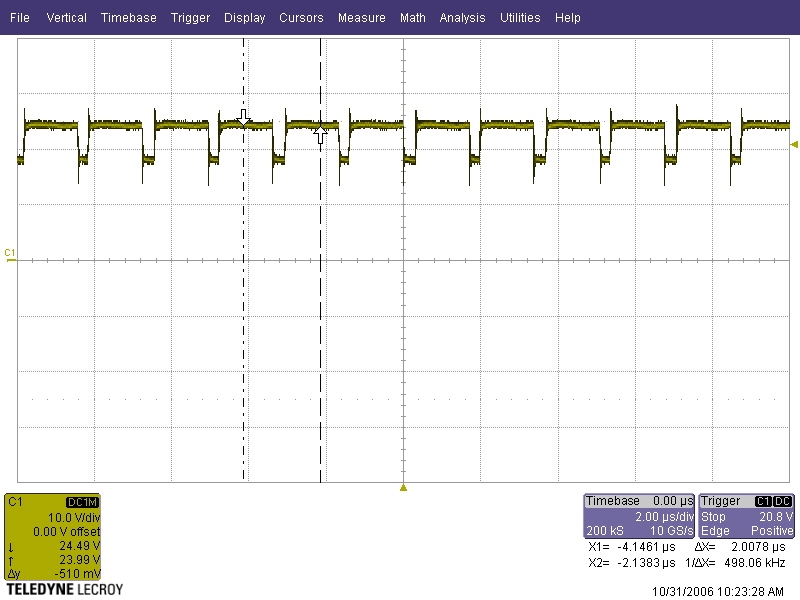
    We think that the bad spectral performance is product from the "wired" switching behaviour:

    (this picture can also be foud in the 'Comparison EvalBrd and HeliSourceSC1.pdf' 4.2.2)

    However, every 8th ON-time (and it's very systematic) is much longer than the other ones and this can be seen in the output spectrum of the LED. The On-times on the EvalBrd were much more similar and thus the spectrum much cleaner.

    Any ideas why the controller may behave like this? Any hint is very appreciated!


    Thanks for helping us solving this problem.


    BR,

    Benjamin

  • Hello Benjamin,

    This is a lot to look through if you could give me some time. But one thing I noticed is that your layout is pretty good, but the input capacitance concerns me. You really want to have the input cap grounds as close as possible to the diode ground. I see you have a 4.7uF there which is good, but I don't think it is sufficient to reduce the switching noise loops in such a small case size when you are running so much current. As an experiment I would add significantly more ceramic capacitance there, maybe a few 10uF 1210 caps in parallel, to see if there is improvement. I don't believe you would need to move the 2.2mF cap if there is sufficient ceramic input caps by the diode.

    I also noticed that the FET and diode you are using may be cutting it close with their ratings. They are fine at 1A for sure, but the Rds(on) of the FET and the case size of the diode may have trouble at 5A. Have you noticed how hot they get? Do you have a thermal camera? If either of them are getting too hot/leaky it could cause strange behavior like this as well. They may be fine, but at 5A I expect they may not be and could be overheating. I will get back to you after I have had more time to look over all of this, but you may want to check those things in the mean time.

    Regards,

    Clint

  • Hello Clint

    Thanks for you advices.

    I measured the temperature of the FET and the schottky diode. Without any heatsink and while driving 4A, the case of the diode is about 97°C and the FET is 91°C. In our product we will add a heatsink for the diode and the FET.
    To make sure I replaced the FET and the Diode and reduced the Output current to 2A. But I still had that irregular switching behavior. So I decided to solder a second setup.

    I used equivalent components and PCB. On this setup I noticed the same switching behavior as on the EvalBoard. Absolutely regularly. The picture below shows you the switching behavior on the new setup.

    Related to this observation. The noise at the output current was reduced and is comparable to the output noise on the EvalBrd.
    On this setup I added five 10uF capacities parallel to the 4.7uF capacity. I didn't noticed any improvements.

    During my measurements I noticed, that the analog dimming is influenced by temperature. The output current is rising, if the temperature is rising.
    I hope that I can suppress this behavior by using an external voltage to set IADJ

    Regards,

    Benjamin

  • Hello Benjamin,

    Were you able to pinpoint the exact differences between your 2 boards? That is strange, but things like that happen here and there. It could be a cold solder joint somewhere, or more commonly with exposed pad devices the DAP doesn't get soldered down well and that will cause noise issues. But I'm glad your second board is working much more as expected.

    Regarding IADJ if you are just using the internal clamp which it looks like it from the schematic then it will vary. That clamp has a temperature coefficient like any zener so it has a noticeable tolerance. That will not be an issue if you use an external reference/voltage. Let me know if you need anything else or if I should close this thread (it is still visible and can still be posted in after it is closed). Thanks.

    Regards,

    Clint

  • Hello Clint

    Thanks for all your advice.  Using an external Voltage for Analog Dim  fixed the temperature dependence.

    There is one last question. I added a bidirectional transient protection diode between GND and VIN 24V (/cfs-file/__key/communityserver-discussions-components-files/196/0245.1884.SMAJ36CA_5F00_Transientenschutzdiode.pdf). Unfortunately I noticed, that after this modification, there is a lot noise between 0 and 50kHz. (Factor 20).
    I detected this problem on my own Board and on the EvalBoard as well.

    Is it possible, that the chip is negatively influenced by the Diode?

    Regards,

    Benjamin

  • Hello Benjamin,

    I don't think the LM3409 is negatively influenced by the TVS. It is more likely the TVS has some parasitic characteristics that is causing the noise. It might be worthwhile to see if it is causing some noise or oscillation on the input versus without it. Is there any way you can scope (not FFT) the input and actually see a difference? If it is an oscillation it should be easy enough to fix. If it is just introducing to much noise (are you trying to pass some EMI requirement?) you may need a filter. Is a TVS required for this application? If so it may be worthwhile to try different ones from different manufacturers as well as they will all have different parasitic characteristics.

    Regards,

    Clint