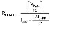
Other Parts Discussed in Thread: TPS92515
Hi Team
TPS92515 is using Constant Off time tech.
if I set ILED = 1A and ILpp = 200mA and VIDJ = 2.4V, Rsense would be 0.218 Ohm.
under such H/W condition,
for "Down Direction",
if the actual load current go down to 0.6A temporarily due to sudden load impedance increase,
TPS92515 can successfully maintain ILED = 1A by duty increase with wide enough duty margin if duty margin is allowed enough.
but,
for "Up Direction",
for an acutual load currect going up case temporarily due to sudden load impedance decrease, TPS92515 will have a only +100mA margin.
so, if a load changes up above 1.1A forever due to forever load impedance decrease, TPS92515 will not successfully maintain ILED = 1A by duty decrease
because the actual load above 1.1A will completely turn off the internal N-Ch FET.
therefore, to secure more larger margin of "Up Direction", we would better increase ILPP, am I right ?
namely, I think for "Up Direction", TPS92515 has only ILPP/2 margin to be covered from ILED, while for "Down Direction, we has more wider margin than "Up Direction" until duty margin is allowed.


