Other Parts Discussed in Thread: LM3406
Hi everyone! I'm working in a project for agricultural applications using a 50[w] led with Vf=31[V] 1.5[A]. I decided to use the LM3406 because it's high input voltage range, dimming capabilities and current.
I designed a PCB to drive the led at its maximum capability (1.5[A]), but right now I am having issues with the output current delivered by my circuit. I am getting 0.12[A] instead the 1.5[A] that I wanted. I am using a controlled power source that delivers 48 [V] with a maximum output current of 4[A] and a ripple of 0.1[V]. When I connect the source to the circuit a lot of noise appears, contaminating the current signal of my device. Do you have any ideas of how to solve this problem?
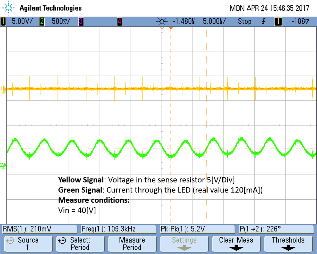
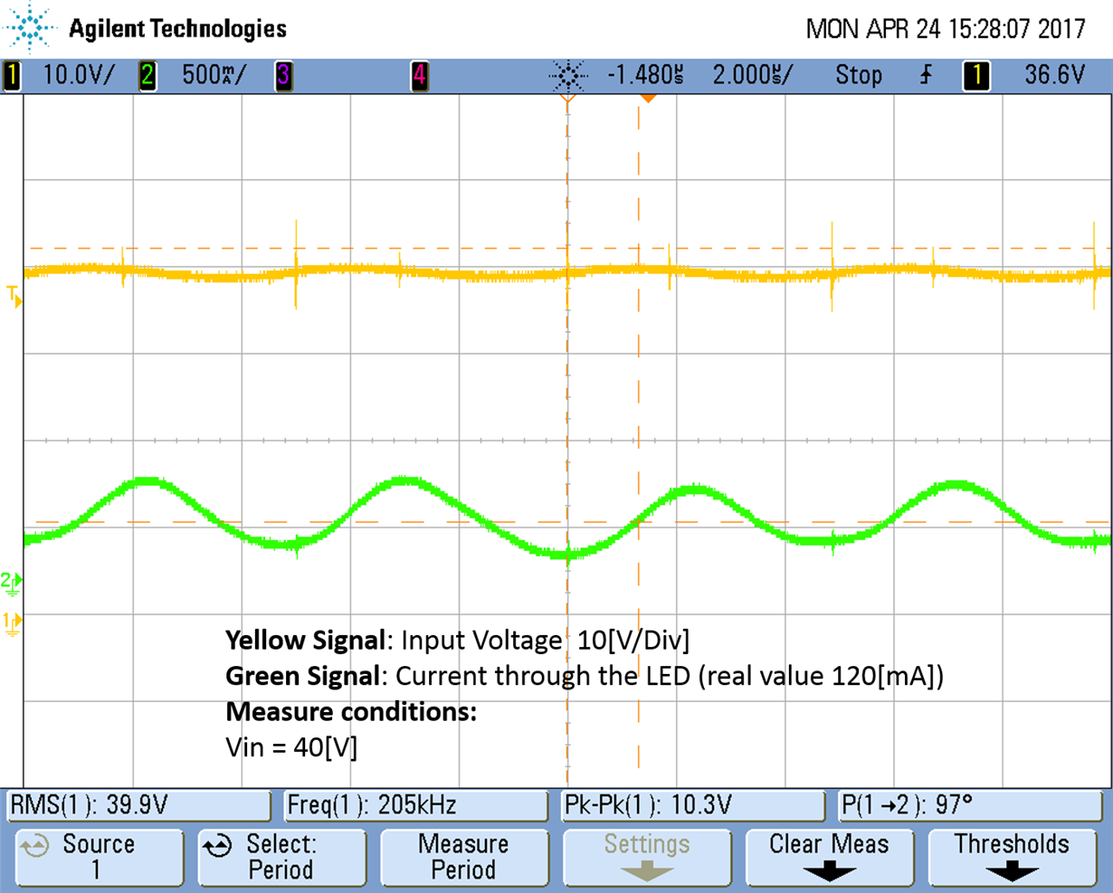
I notice that when I rise the input voltage (from 0[V] to 48[V]) I get a maximum current of 1[A] at 38[V], then it decrease to 0.2[A] at 48[V]. When I rise the voltage, the noise rise too, reaching a maximum value of 20[V] peak to peak. (So the input voltage varies from 38[V] to 58[V])
I also notice that when I put an input voltage over 38[V], the current through the led start operating in discontinuous mode. I think its because the over-voltage/over-current comparator system used by the driver. The input voltage noise produced also generates noise in the sense resistor voltage, exceeding the 300[mV] that this system tolerates. I Also think about "power supply interactions" between the power source and the device, but I tried with different input capacitor (according to the calculations) and the conditions did not get better. When I turn on my device, a lot of noise gets into the electrical system.
The design conditions of the project are the follows:
1) I only must use one layer (top layer in this case).
2) I need a fast response of the current. I want to test the dimmer of the drive and compare it with a high response mosfet. I want to operate the drive in a current range from 0.3[A] to 1.5[A]
3) Minimum noise injection to the electrical system.
4) Input voltage of 48[V].
I attach some oscilloscope shoots of the signals, my schematic and PCB design.
Notice that the current measures showed in the pictures are scaled (I turn more rounds in the current sensor).
I tried to solve the problem putting a parallel capacitor to the sense resistor. When I put the capacitor close to the resistor, the signal did not improve, but when I put close to the CS pin, I can get more current. (actually, that is one of the reasons why I get 1[A] at 38[V]. I also change the input capacitor to the minimum value recommended by the datasheet of the driver (equation 15). The signal improves, but the problem continues.
What do you think of my design? I am using components with a 1206 size. I designed the vias with a width of 71 [mil] for the current with 1oz of copper. I calculated that for 1.5[A] a need 7[mil] with 3oz of copper, and 12[mil] for 2oz of copper (The problem is that 3oz copper is far more expensive). The vias can produce some problems? How much far I have to put the components from the drive?
If you can give me some advises or recommendations I will be very grateful.


